| 100-00 General Information | 2014 Fiesta |
| Description and Operation | Procedure revision date: 04/3/2013 |
Symbols are used inside the graphics and in the text area to enhance the information display.
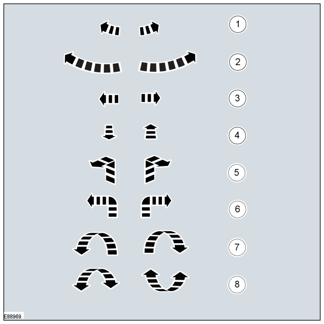
Movement Symbols
Movement symbols provide detailed information to a required component movement. These component movements can be rotational or 1-3 dimensional movements.
| Item | Part Number | Description |
|---|---|---|
| 1 | — | Minor component movement clockwise/counterclockwise |
| 2 | — | Major component movement clockwise/counterclockwise |
| 3 | — | Component movement to the left/right/up/down |
| 4 | — | Component movement towards/away |
| 5 | — | 3 dimensional component movement |
| 6 | — | 2 dimensional component movement |
| 7 | — | 3 dimensional component rotation |
| 8 | — | 3 dimensional component cycling |
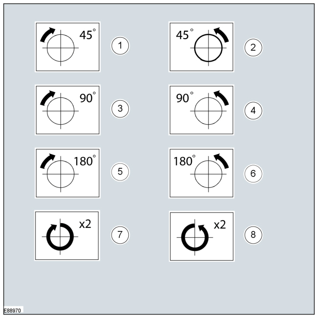
Turn Symbols
Turn symbols are used to provide further information on the direction or angle of component turns.
| Item | Part Number | Description |
|---|---|---|
| 1 | — | Turn the component clockwise through 45° |
| 2 | — | Turn the component counterclockwise through 45° |
| 3 | — | Turn the component clockwise through 90° |
| 4 | — | Turn the component counterclockwise through 90° |
| 5 | — | Turn the component clockwise through 180° |
| 6 | — | Turn the component counterclockwise through 180° |
| 7 | — | Turn the component clockwise through 2 complete turns |
| 8 | — | Turn the component counterclockwise through 2 complete turns |
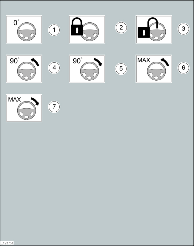
Steering Wheel Symbols
Steering wheel symbols are used to provide further information to a required steering wheel position or steering column lock status.
| Item | Part Number | Description |
|---|---|---|
| 1 | — | Steering wheel in straight ahead position |
| 2 | — | Steering column lock locked |
| 3 | — | Steering column lock unlocked |
| 4 | — | Turn the steering wheel to the 90° left position |
| 5 | — | Turn the steering wheel to the 90° right position |
| 6 | — | Turn the steering wheel to the left-hand end position |
| 7 | — | Turn the steering wheel to the right-hand end position |
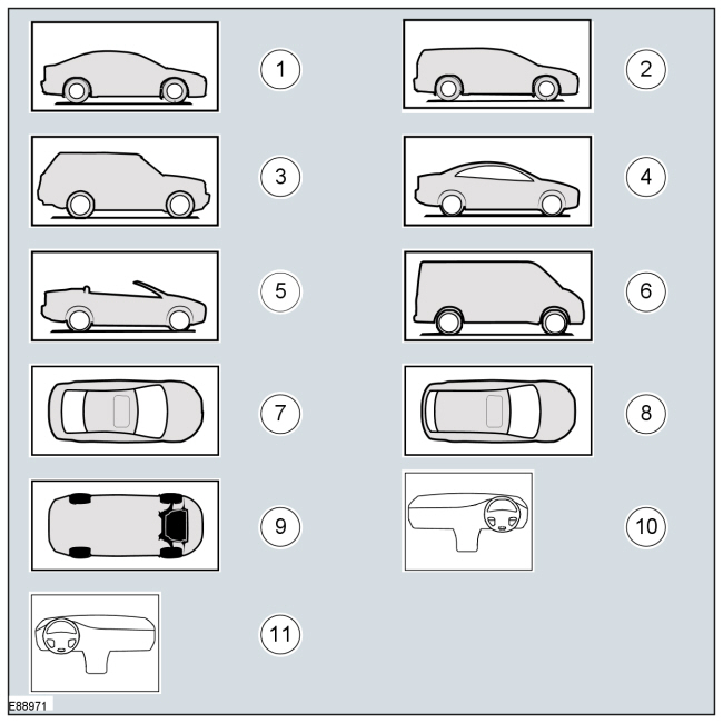
Body Types
Body type symbols are used to identify different body configurations.
| Item | Part Number | Description |
|---|---|---|
| 1 | — | 3, 4, 5-door body style |
| 2 | — | Wagon body style |
| 3 | — | Sports utility vehicle body style |
| 4 | — | Coupe body style |
| 5 | — | Convertible body style |
| 6 | — | Van body style |
| 7 | — | 3, 4, 5-door body style - Top View |
| 8 | — | Wagon body style - Top View |
| 9 | — | Underview |
| 10 | — | Right-hand drive (RHD) vehicle |
| 11 | — | Left-hand drive (LHD) vehicle |
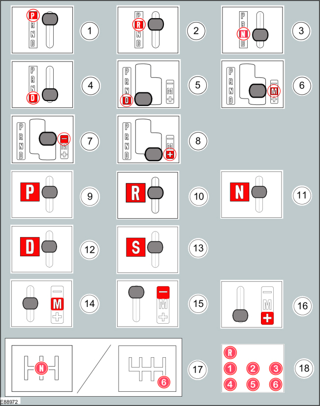
Gearshift lever and selector lever position symbols
Gearshift lever and selector lever position symbols are used to show the lever position that is required to be selected to carry out a procedure step.
| Item | Part Number | Description |
|---|---|---|
| 1 | — | Replaced by symbol 9 |
| 2 | — | Replaced by symbol 10 |
| 3 | — | Replaced by symbol 11 |
| 4 | — | Replaced by symbol 12 |
| 5 | — | Replaced by symbol 12 |
| 6 | — | Replaced by symbol 14 |
| 7 | — | Replaced by symbol 15 |
| 8 | — | Replaced by symbol 16 |
| 9 | — | Set the selector lever to the park (P) position |
| 10 | — | Set the selector lever to the reverse ( R ) position |
| 11 | — | Set the selector lever to the neutral (N) position |
| 12 | — | Set the selector lever to the drive (D) position |
| 13 | — | Set the selector lever to the drive (S) position |
| 14 | — | Set the selector lever to the drive (M) position |
| 15 | — | Set the selector lever to the drive (-) position |
| 16 | — | Set the selector lever to the drive (+) position |
| 17 | — | Set the gearshift lever to the neutral (N) position |
| 18 | — | Further gearshift lever positions that may appear in illustrations |
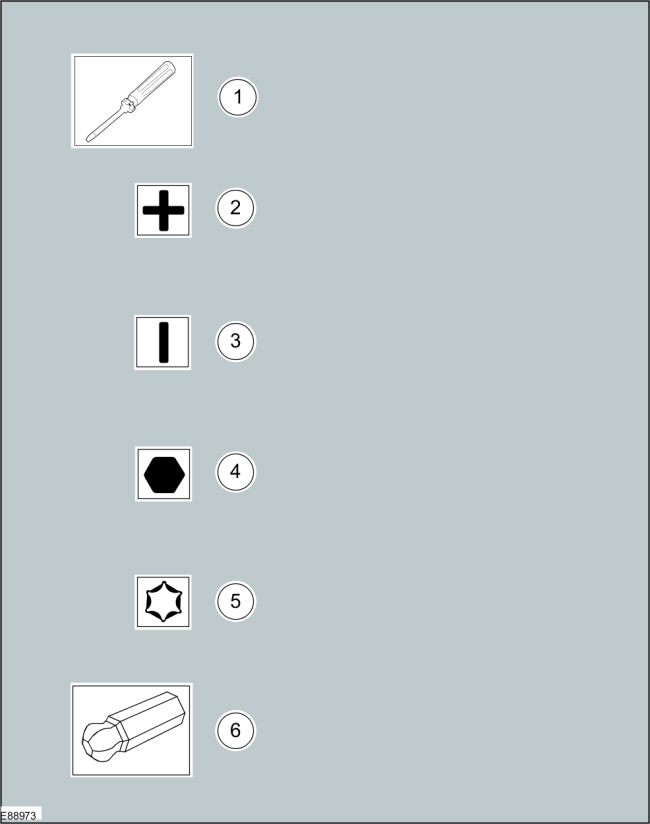
Screwdriver symbols
The screwdriver symbols are used to show which screwdriver bit is recommended to carry out a procedure step.
| Item | Part Number | Description |
|---|---|---|
| 1 | — | Screwdriver |
| 2 | — | Cross bladed screwdriver |
| 3 | — | Flat bladed screwdriver |
| 4 | — | Hexagonal screwdriver |
| 5 | — | TORX screwdriver |
| 6 | — | Ball drive hex bit |
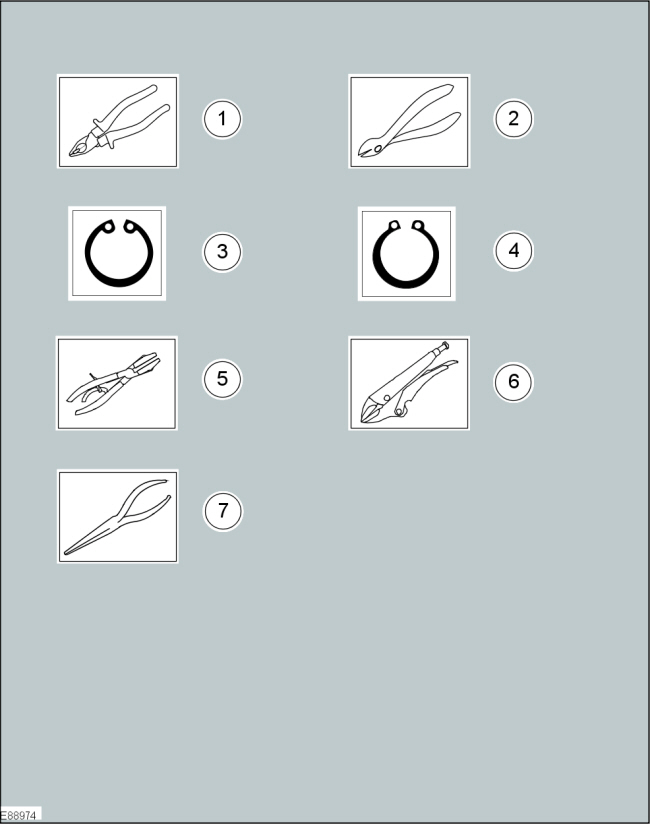
Pliers symbols
The pliers symbols are used to show which pliers is recommended to carry out a procedure step.
| Item | Part Number | Description |
|---|---|---|
| 1 | — | Combination pliers |
| 2 | — | Side cutter pliers |
| 3 | — | Securing ring - inner |
| 4 | — | Securing ring - outer |
| 5 | — | Hose clamp pliers |
| 6 | — | Locking pliers |
| 7 | — | Long nose pliers |
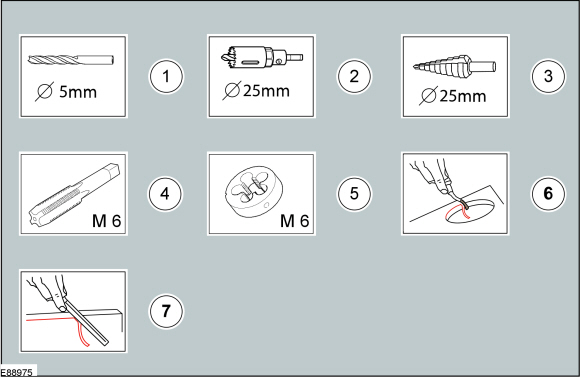
Drill symbols
The drill symbols are used to show which type and size of drill bit is recommended to carry out a procedure step.
| Item | Part Number | Description |
|---|---|---|
| 1 | — | Drill bit with a specified diameter |
| 2 | — | Hole saw with a specified diameter |
| 3 | — | Stepped drill bit with a specified diameter |
| 4 | — | Tap with a specified diameter |
| 5 | — | Die with a specified diameter |
| 6 | — | Scraper for circular holes |
| 7 | — | Scraper for straight edges |
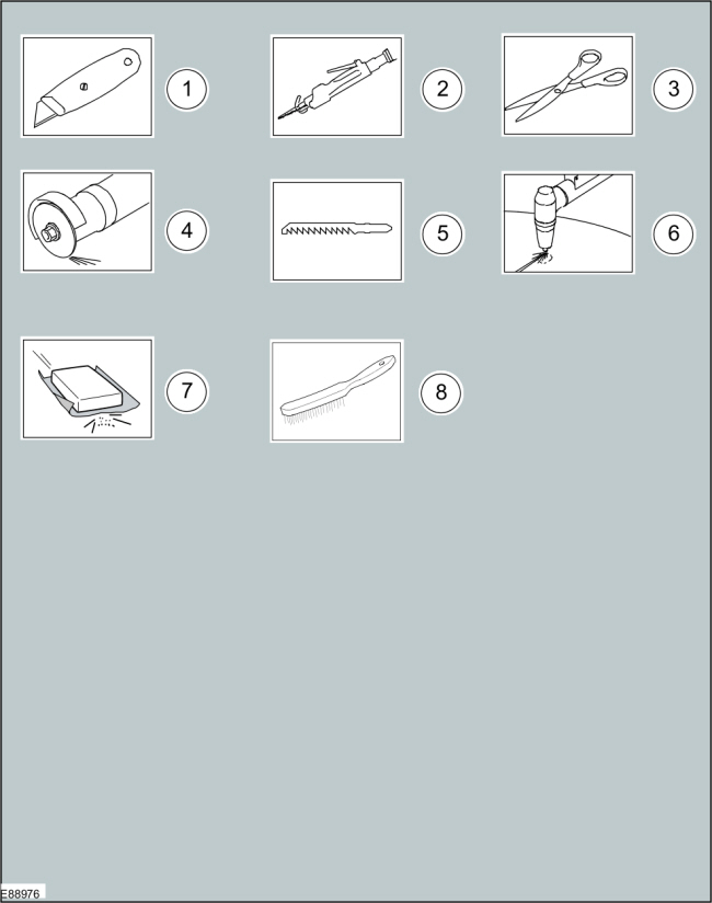
Cutting tool symbols
The cutting tool symbols are used to show which type of cutting tool is recommended to carry out a procedure step.
| Item | Part Number | Description |
|---|---|---|
| 1 | — | Cutting knife |
| 2 | — | Air body saw |
| 3 | — | Scissors |
| 4 | — | Grinder |
| 5 | — | Jig saw |
| 6 | — | Plasma cutter |
| 7 | — | Sanding Paper |
| 8 | — | Wire brush |
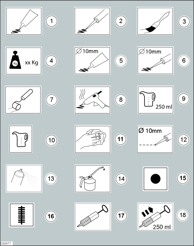
Apply Chemical or load symbols
The apply chemical or load symbols are used to show where to apply which type of chemical or load to carry out a procedure step.
| Item | Part Number | Description |
|---|---|---|
| 1 | — | Apply the substance from the specified tube |
| 2 | — | Apply the substance from the specified cartridge |
| 3 | — | Apply the specified chemical with a brush |
| 4 | — | Apply the specified load to the specified component |
| 5 | — | Apply a bead with a specific diameter from the specified tube |
| 6 | — | Apply a bead with a specific diameter from the specified cartridge |
| 7 | — | Apply the specified chemical with a roller |
| 8 | — | Apply hot glue to the specified component |
| 9 | — | Apply the specified amount of fluid from the fluid can |
| 10 | — | Apply fluid from the fluid can |
| 11 | — | Clean the specified component with the specified material |
| 12 | — | Apply a broken bead from the specified tube |
| 13 | — | Apply the specified chemical from a spray can |
| 14 | — | Apply the specified lubricant to the specified component |
| 15 | — | Apply spot welds to the specified component |
| 16 | — | Apply a continuous weld to the specified component |
| 17 | — | Handle the fluid using a syringe |
| 18 | — | Extract the specified amount of fluid using a syringe |
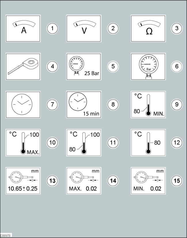
Measurement symbols
The measurement symbols are used to show where to measure which type of measurement to carry out a procedure step.
| Item | Part Number | Description |
|---|---|---|
| 1 | — | Measure the current using a digital multimeter |
| 2 | — | Measure the voltage using a digital multimeter |
| 3 | — | Measure the resistance using a digital multimeter |
| 4 | — | Measure the length/distance |
| 5 | — | Check that the specified pressure is available using a suitable pressure gauge |
| 6 | — | Measure the pressure at the specified port using a suitable pressure gauge |
| 7 | — | Measure the time using a suitable stopwatch |
| 8 | — | Wait for the specified period of time |
| 9 | — | The specified task requires the specified minimum temperature |
| 10 | — | The specified task requires the specified maximum temperature not to be exceeded |
| 11 | — | The specified task requires the specified temperature range |
| 12 | — | The specified task requires the specified temperature |
| 13 | — | Measure and check for the specified value using a dial indicator gauge |
| 14 | — | Measure and check for the specified MAX value using a dial indicator gauge |
| 15 | — | Measure and check for the specified MIN value using a dial indicator gauge |
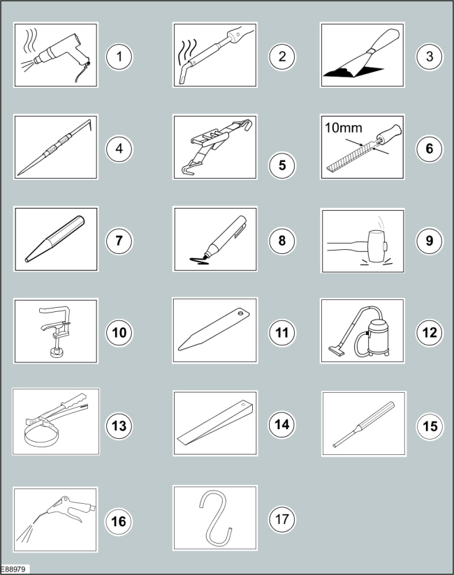
General equipment symbols
The general equipment symbols are used to show where to use which type of general equipment to carry out a procedure step.
| Item | Part Number | Description |
|---|---|---|
| 1 | — | Hot air gun |
| 2 | — | Soldering iron |
| 3 | — | Scraper |
| 4 | — | Scriber |
| 5 | — | Securing strap |
| 6 | — | File with a specified size |
| 7 | — | Center punch |
| 8 | — | Marker |
| 9 | — | Mallet |
| 10 | — | Hose clamp |
| 11 | — | Interior trim remover |
| 12 | — | Vacuum cleaner |
| 13 | — | Strap wrench |
| 14 | — | Wedge |
| 15 | — | Pin Punch |
| 16 | — | Air blow gun |
| 17 | — | Relocate and support the component |
| 18 | — | C-clamp |
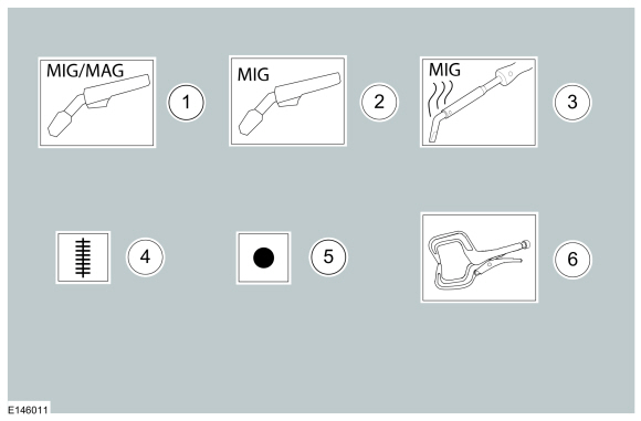
Welding symbols
These symbols indicate the type of welding to be used.
| Item | Part Number | Description |
|---|---|---|
| 1 | — | Metal inert gas (MIG) / Metal active gas (MAG) welding equipment |
| 2 | — | Metal inert gas (MIG) welding equipment |
| 3 | — | Metal inert gas (MIG) brazing equipment |
| 4 | — | Apply a continuous weld to the specified component |
| 5 | — | Apply spot welds to the specified component |
| 6 | — | C-clamp |
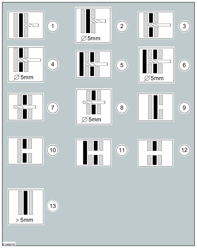
Drilling and grinding symbols
These symbols indicate the type of drilling or grinding to be used.
| Item | Part Number | Description |
|---|---|---|
| 1 | — | Drill through first body layer with a suitable diameter |
| 2 | — | Drill through first body layer with the specified diameter |
| 3 | — | Drill through the indicated number of body layers with a suitable diameter |
| 4 | — | Drill through the indicated number of body layers with the specified diameter |
| 5 | — | Drill through the indicated number of body layers with a suitable diameter |
| 6 | — | Drill through the indicated number of body layers with the specified diameter |
| 7 | — | Drill through all body layers with a suitable diameter |
| 8 | — | Drill through all body layers with the specified diameter |
| 9 | — | Grind one layer |
| 10 | — | Grind two layers |
| 11 | — | Grind to last layer |
| 12 | — | Grind all layers |
| 13 | — | Material thickness > Xmm |
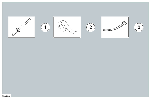
Material symbols
The material symbols are used to show where to use which type of material to carry out a procedure step.
| Item | Part Number | Description |
|---|---|---|
| 1 | — | Remove/Install the specified blind rivet |
| 2 | — | Apply tape to the specified component/area |
| 3 | — | Remove/Install the specified cable tie |
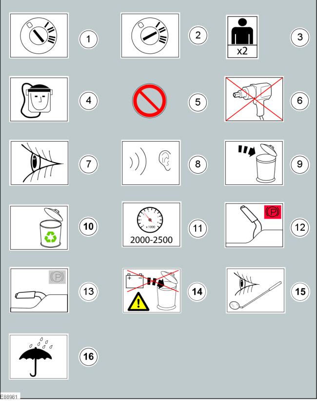
Miscellaneous symbols
These symbols provide further information that is required to carry out a procedure step.
| Item | Part Number | Description |
|---|---|---|
| 1 | — | Set the ignition switch to the 0 position |
| 2 | — | Set the ignition switch to the II position |
| 3 | — | The procedure step requires the aid of the specified number of supporting technicians |
| 4 | — | Self contained breathing apparatus |
| 5 | — | General prohibition used in combination with another symbol |
| 6 | — | Do not use power tools |
| 7 | — | Visual check |
| 8 | — | Noise check |
| 9 | — | Dispose the specified component |
| 10 | — | Replaced by item 9 (Dispose the specified component) |
| 11 | — | Set the engine speed to the specified value |
| 12 | — | Fully apply the parking brake lever |
| 13 | — | Fully release the parking brake lever |
| 14 | — | Do not dispose of batteries into the waste bin |
| 15 | — | Visual check using a mirror |
| 16 | — | Area/component must be dry |
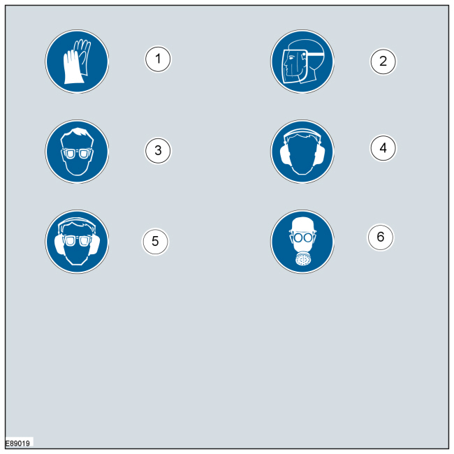
Mandatory Protective equipment - Health and safety symbols
The protective equipment symbols advise to use a mandatory protective equipment to avoid or at least reduce possible health and safety risks.
| Item | Part Number | Description |
|---|---|---|
| 1 | — | Wear protective gloves |
| 2 | — | Wear face guard |
| 3 | — | Wear safety goggles |
| 4 | — | Wear ear protectors |
| 5 | — | Wear safety goggles and ear protectors |
| 6 | — | Wear a respirator |
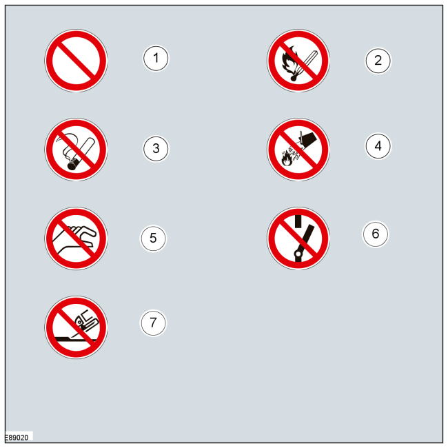
Prohibition - Health and safety symbols and component damage
The prohibition symbols are used to prohibit the specified actions to avoid or at least reduce possible component damage and health and safety risks.
| Item | Part Number | Description |
|---|---|---|
| 1 | — | General prohibition symbol |
| 2 | — | No naked flames |
| 3 | — | No smoking |
| 4 | — | No water |
| 5 | — | Do not touch |
| 6 | — | Do not switch |
| 7 | — | No grinding |
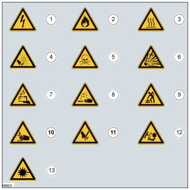
Warning symbols - Health and safety and component damage
The warning symbols are used to advise on hazardous conditions to avoid or at least reduce possible component damage and health and safety risks.
| Item | Part Number | Description |
|---|---|---|
| 1 | — | Hazardous voltage/Electrical shock/Electrocution |
| 2 | — | Fire Hazard/Highly flammable |
| 3 | — | Burn hazard/Hot surface |
| 4 | — | Automatic start-up |
| 5 | — | Toxic |
| 6 | — | Explosive material |
| 7 | — | Battery hazard |
| 8 | — | Corrosive material |
| 9 | — | Lifting hazard |
| 10 | — | Hand crush/Force from above |
| 11 | — | Cutting of fingers or hand |
| 12 | — | Pressure hazard |
| 13 | — | Invisible laser radiation. Do not view directly with optical instruments (magnifiers). Class 1M laser product |
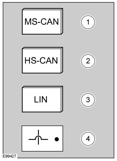
Control Diagram symbols - Description and Operation procedures
These symbols provide further information on the type of connectivity, direction of flow or type of data bus of a system.
| Item | Part Number | Description |
|---|---|---|
| 1 | — | Mid-speed Controller Area Network (CAN) |
| 2 | — | High-speed Controller Area Network (CAN) |
| 3 | — | Local Interconnect Network (LIN) |
| 4 | — | Wires crossing not connected |
Copyright © Ford Motor Company