| 413-01 Instrumentation, Message Center and Warning Chimes | 2014 Fiesta |
| Description and Operation | Procedure revision date: 05/21/2013 |
System Operation
System Diagram - Gauges
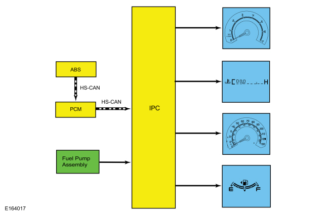
Network Message Chart - Gauges
Module Network Input Messages - IPC
| Broadcast Message | Originating Module | Message Purpose |
|---|---|---|
| Engine coolant temperature | PCM | Engine temperature data used for temperature gauge indication. |
| Engine rpm | PCM | Engine speed data used for tachometer indication. |
| Ignition status | BCM | Ignition RUN, START and accessory states required for the IPC operating modes and fault reporting. |
| Vehicle speed | ABS module | Vehicle speed data used for speedometer indication. |
| Wheel speed data | ABS module | Input used for calculating the rolling odometer count which is used to generate the vehicle speed data. |
System Diagram - Indicators
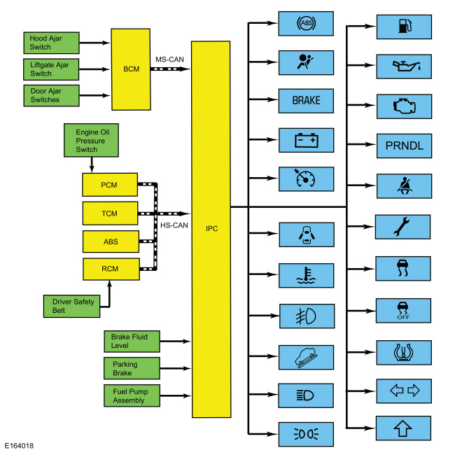
Network Message Chart - Indicators
Module Network Input Messages - IPC
| Broadcast Message | Originating Module | Message Purpose |
|---|---|---|
| ABS warning indicator request | ABS module | Input used to control the ABS warning indicator. |
| Airbag warning indicator | RCM | Input used to control the airbag warning indicator. |
| Brake warning indicator request | ABS module | Input used for the ABS input to control the brake warning indicator. |
| Charge indicator | BCM | Input used to control the charging system warning indicator. |
| Cruise control status | PCM | Input used to control the cruise control indicator. |
| Door ajar status | BCM | Input used to control the door ajar warning indicator. |
| Driver safety belt buckle status | RCM | Input used to control the safety belt warning indicator. |
| Engine coolant temperature | PCM | Input used to control the engine over-temperature indicator. |
| Engine oil pressure indicator | PCM | Input used to control the low oil pressure warning indicator. |
| Engine warning indication | PCM | Input used for the engine fault input to control the powertrain malfunction (wrench) indicator. |
| Front fog lamp indicator | BCM | Input used to control the fog lamp indicator. |
| High beam status | BCM | Input used to control the high beam indicator. |
| Lights on indicator | BCM | Input used to control the lights on indicator. |
| MIL request | PCM | Input used to control the MIL . |
| Stability-traction control indicator request | ABS module | Input used to control the stability-traction control indicator (sliding car icon). |
| Stability-traction control disabled indicator request | ABS module | Input used to control the stability-traction control disabled indicator (sliding car OFF icon). |
| Tire pressure warning indicator | BCM | Input used to control the TPMS indicator |
| Transmission fault indication | TCM | Input used for the transmission fault input to control the powertrain malfunction (wrench) indicator. |
| Transmission shift indicator lamp | PCM | Input used to control the upshift indicator in the integrated LCD . |
| Transmission shift mode | TCM | Input used to control the grade assist indicator. |
| Transmission gear lever position | TCM | Input used to control the PRNDL indication in the integrated LCD . |
| Turn indication data | BCM | Input used to control the RH / LH turn or hazard indicators. |
Gateway Function
The IPC acts as a gateway module by receiving information in one format and transmitting it to other vehicle modules using another format. This enables network communication between modules that do not communicate using the same network ( HS-CAN , Infotainment Controller Area Network (I-CAN) or MS-CAN ).
Networked Input Messages and Default States
NOTE: Whenever a network message is suspected as missing and confirmed by a missing message DTC (U-code), it is important to look for other symptoms that can also be present in the IPC and throughout the vehicle. Once a DTC sets in the IPC , it can be helpful to review the complete message list to determine which other modules also rely on the same message and run the self-test for those modules. If the message is missing from other modules, the same DTC can also be set in those modules. Confirmation of missing messages common to multiple modules can indicate that the originating module is the source of the concern or the communication network may be faulted.
The IPC uses input messages from other modules to control the gauges, informational indicators, warning indicators and message center message displays over the communication networks. Network messages can drop out or be missing for a variety of reasons, such as high network traffic on the bus. The IPC incorporates a defined strategy for handling missing network messages based on time. The required time for a network message to be missing differs between the various gauges, indicators and message center displays. The strategy is basically the same for all types of indication but differs in the length of time required for the network message to be missing. If a required network message is missing or invalid for less than the preset time criteria, the gauge or indicator that requires the network message remains at the last commanded state based upon the last network message received. The example below describes how the stability-traction control indicator (sliding car icon) functions using a time criteria of 5 seconds.
If the stability-traction control network message is missing for less than 5 seconds and the stability-traction control indicator (sliding car icon) was on, the indicator remains in the on state until the next network message is received. Again, using the time criteria example, if the network message remains missing or invalid for more than 5 seconds, the IPC sets a U-code DTC and the IPC output becomes a default action for the indicator or gauge. The indicator may default on/off or the gauge may default to the rest position.
Each indicator or gauge utilizes a different default strategy depending on the nature of the indication. Refer to the diagnostic overview descriptions located before each individual pinpoint test for further description of the default action specific to each indicator or gauge. If the missing messaged input to the IPC returns at any time, the normal function of the gauge or indicator resumes.
In order to diagnose a messaged network concern, it is very important to understand:
Factory-Transport Mode
Factory mode is used during the vehicle build to enable the assembly plant to carry out certain functions. Once the vehicle
build is complete, the vehicle is placed in transport mode to reduce the drain on the battery. Transport mode is controlled
by the
IPC
. When the vehicle is in transport mode, the
IPC
displays a message in the integrated
LCD
, indicating the vehicle is in transport mode. To take the vehicle out of transport mode and place into normal operation mode,
Refer to:
Transport and Factory Mode Deactivation
(419-10 Multifunction Electronic Modules, General Procedures).
Configuration
The
IPC
contains configurable items. Configurable items often include customer preference items, which can also be set with a scan
tool. The remaining configurable items can only be set through the car configuration parameters.
Refer to:
Module Configuration - System Operation and Component Description
(418-01 Module Configuration, Description and Operation).
Prove-Out
The IPC and other modules carry out a display prove-out to verify all module controlled warning/indicator lamps and monitored systems are functioning correctly within the IPC . The IPC and other modules, such as the RCM , provide a timed prove-out of some indicators while other indicators illuminate until engine start up. When the ignition is cycled to on with the engine off, the indicators illuminate to prove-out according to the following table:
| Indicator | Indicator Type | Prove-Out Duration |
|---|---|---|
| ABS | Warning | 3 seconds |
| Airbag | Warning | 8 seconds |
| Brake | Warning | 3 seconds |
| Charge | Warning | Engine startup |
| Cruise control | Informational | 3 seconds |
| Door ajar | Warning | None |
| Engine over-temperature | Warning | 3 seconds |
| Fog lamp | Informational | None |
| Grade assist | Informational | 3 seconds |
| High beam | Informational | None |
| Lights on | Informational | None |
| Low fuel | Warning | 3 seconds |
| Low oil pressure | Informational | Engine startup |
| MIL | Warning | Engine startup |
| Powertrain malfunction (wrench) | Informational | 3 seconds |
| Safety belt | Warning | 60 seconds if the safety belt is unbuckled, turns off when the safety belt is buckled (controlled by the RCM ) |
| Stability/traction control (sliding car icon) | Warning | 3 seconds |
| Stability/traction control disabled (sliding car OFF icon) | Informational | 3 seconds |
| TPMS | Warning | 3 seconds |
| RH / LH turn | Informational | None |
Dealer Test Mode
To enter the IPC dealer test mode, begin with the ignition in the OFF mode. Press and hold the IPC TRIP/RESET button. Place the ignition in the RUN mode and hold the TRIP/RESET button until the display indicates tESt, usually within 3 to 5 seconds. Press the TRIP/RESET button once to advance through each stage of the self-test. To exit the IPC dealer test mode, turn the ignition to the OFF position.
NOTE: The displays listed in the table below use xxx's to represent a numeric or alpha-numeric value. The value may display the same amount of characters represented by the xxx's or there may be more/less depending on the type of display. For example, DTC xxxx xxxx xxxx may display DTC C0100. Note there are 12 x's in the display description but only 4 digits in the actual display.
| IPC Display | Description |
|---|---|
| Test | Initial entry display into the dealer test mode. |
| Gauge | Carries out the gauge sweep of analog gauge(s), then displays the present gauge value(s). |
| LED | Illuminates all the microprocessor controlled LED indicators. |
| ROM level | Displays the hexadecimal ROM level. For a ROM checksum fault, FAIL displays on the bottom line |
| NVM target ROM | Displays the hexadecimal ROM level and type as stored in NVM . For an NVM checksum fault is detected, FAIL displays on the bottom line |
| NVM EEPROM level | Displays the hexadecimal value for the EEPROM level. For an NVM checksum fault, FAIL displays on the bottom line |
| Manufacturing date | Displays the hexadecimal coding of the final manufacturing test date. |
| DTC | Displays Diagnostic Trouble Codes (DTCs) detected in continuous operation not during self-test. |
| Speed mph | Displays the English speed value being inputs in tenths of mph to the IPC , the speedometer indicates the present filtered speed. |
| Speed km/h | Displays the metric speed value being inputs in tenths of km/h to the IPC , the speedometer indicates the present filtered speed. |
| Speedometer | Displays corresponding speedometer gauge driver counts output for present filtered speed. |
| Engine rpm | Displays the tachometer value being input in rpm to the IPC , tachometer indicates the present filtered rpm. |
| Tachometer | Displays corresponding tachometer driver counts output for present filtered engine rpm. |
| Odometer | Displays the odometer rolling count input to the IPC . |
| Fuel analog/digital input | Displays the present fuel level analog/digital input in decimal. The IPC indicates the present fuel level. |
| Fuel gauge | Displays corresponding fuel gauge driver counts output for present filtered fuel level. |
| Fuel flow | Displays the present filtered fuel flow status in decimal (used for DTE calculation). |
| Fuel percent | Displays the present fuel level percent status in decimal. |
| Engine temperature | Displays the last temperature gauge input value from the HS-CAN in degrees C, temperature gauge indicates the present filtered temperature. |
| Temperature gauge | Displays corresponding temperature gauge driver counts output for present filtered temperature value. |
| Battery voltage | Displays the present battery monitor reading in volts. |
| Analog/digital input | Displays hexadecimal value of the analog/digital port input reads. |
| Personality input | Displays the vehicle configuration for the personality settings. |
| Port input | Displays hexadecimal value of the digital port reads. |
| DTE | Displays the calculated DTE . |
| Average fuel economy | Displays the running average fuel economy in decimal. |
| PATS | Displays the current PATS settings. |
| Manufacturing start date | Displays the hexadecimal manufacturing start date. |
Fuel Gauge
The fuel gauge is an analog gauge. The IPC sends a reference voltage to the fuel level sender. As the fuel level changes, a float actuates the variable resistor on the fuel level sender, raising or lowering the fuel level signal voltage. The IPC monitors the change in voltage and changes the fuel gauge indication with a corresponding movement of the pointer.
The fuel gauge indicates fuel changes quickly while the vehicle is stopped with the engine running. The fuel gauge does not change fuel level indication between key cycles if the vehicle is parked on a slope and does not change fuel indication by more than 1/8 tank when the vehicle ascends or descends a hill.
Tachometer
The tachometer is an analog gauge. The IPC receives the engine rpm message from the PCM over the HS-CAN . The PCM receives the engine rpm data from the CKP sensor.
Temperature Gauge
The temperature gauge is a digital image in the bottom of the LCD display area. The IPC receives the engine coolant temperature data from the PCM over the HS-CAN . The PCM receives the engine coolant temperature data from the ECT sensor.
Speedometer
The speedometer is an analog gauge. The IPC receives the vehicle speed data from the PCM over the HS-CAN . The PCM receives the vehicle speed data from the ABS module over the HS-CAN . The PCM uses tire size stored in the vehicle configuration file along with vehicle speed input to generate a vehicle speed signal.
The IPC provides a tolerance that allows the speed indication to display between 3% below and 7% above the actual vehicle speed. This means that with an actual vehicle speed of 96.6 km/h (60 mph), the speedometer can indicate between 94-103 km/h (58-64 mph). Incorrect tire size or tire size configuration could potentially affect the speedometer accuracy.
Odometer
The IPC receives the odometer count data from the PCM over the HS-CAN . The PCM receives the wheel rotation count data from the ABS module over the HS-CAN and uses other factors such as tire size configuration to generate the odometer count data. The IPC monitors the odometer count input from the PCM and commands the odometer with a numeric display in the IPC LCD display area.
ABS Warning Indicator
The IPC receives the ABS warning indicator request message from the ABS module over the HS-CAN . If a fault condition exists in the ABS , the ABS module sends the ABS warning indicator request message to either flash or illuminate the ABS warning indicator.
Refer to ABS /Brake/Stability-Traction Control System Indication description for a summary of the conditions when the ABS warning indicator is illuminated.
ABS /Brake/Stability-Traction Control System Indication
The ABS , brake and stability-traction control system indication is controlled by both the IPC and the ABS module. The ABS module can illuminate multiple indicators for various fault conditions. The following table provides a summary of the basic fault conditions and the indicators that are illuminated for each condition.
NOTE: Refer to the Normal Operation and Fault Condition description before each brake/stability-traction control system indicator Pinpoint Test (PPT) for the IPC default action for network/missing message conditions.
| Event/Fault Condition | ABS Warning Indicator Status | Brake Warning Indicator Status | Stability-Traction Control Indicator Status | Stability-Traction Control Disabled Indicator Status |
|---|---|---|---|---|
| Parking brake applied | Off | On | Off | Off |
| Low brake fluid level | Off | On | Off | Off |
| Stability-traction control event | Off | Off | Flashing (fast) | Off |
| Stability-traction control disabled by driver | Off | Off | Off | On |
| Single wheel speed sensor faults | On | Off | On | Off |
| 2 or 3 wheel speed sensor faults | On | On | On | Off |
| HCU valve fault | On | On | On | Off |
| ABS module fault | On | On | On | Off |
| HCU pressure sensor fault (master cylinder pressure input) | On | Off | On | Off |
| ABS battery voltage faults | On | On | On | Off |
| ABS pump motor fault | On | Off | On | Off |
| Steering wheel angle sensor center not found fault | Off | Off | On | Off |
| Parking brake position switch fault (open switch condition) | Off | Off | Off | Off |
| Vehicle Identification Number (VIN) mismatch | On | Off | On | Off |
| Incorrect vehicle configuration | On | On | On | Off |
| Stability control calibration file not flashed | On | Off | Flashing (slow) | Off |
| Longitudinal acceleration sensor not calibrated | Flashing (slow) | Off | Flashing (fast) | Off |
| Hill start assist disabled by the ABS module (hill start assist fault) | Off | Off | Off | Off |
Airbag Warning Indicator
The IPC receives the airbag warning indicator request from the RCM over the HS-CAN . If a SRS concern is detected, the RCM sets a DTC and sends the IPC the airbag warning indicator request to illuminate the airbag warning indicator.
Brake Warning Indicator
The IPC uses 3 inputs to control the brake warning indicator. The first 2 inputs are the parking brake position switch and the brake fluid level switch, which are hardwired to the IPC . The third input is the brake warning indicator request message sent from the ABS module over the HS-CAN .
The parking brake position switch and the brake fluid level switch are hardwired to the IPC through a single signal circuit while using a separate ground to control the input.
The IPC provides reference voltage to both the parking brake position switch and the brake fluid level switch.
When the ABS module detects a base brake system concern or other ABS -related concerns that affect the EBD function, the ABS module sends the brake warning indicator request to the IPC over the HS-CAN . The IPC illuminates the brake warning indicator when the brake warning indicator request is received.
Refer to ABS /Brake/Stability-Traction Control System Indication description for a summary of the conditions when the brake warning indicator is illuminated.
Charging System Warning Indicator
The IPC receives the charging system indicator request from the PCM over the HS-CAN . When a fault is detected in the charging system, the PCM sends the IPC the charging system indicator request to illuminate the charging system warning indicator.
Cruise Control Indicator
The IPC receives the cruise control status message from the PCM over the HS-CAN . When the cruise control is active, the PCM sends the IPC the cruise control status message to illuminate the cruise control indicator.
Engine Over-Temperature Warning Indicator
The IPC receives the engine coolant temperature data from the PCM over the HS-CAN . When the engine temperature is in the hot or over heated range, the PCM sends the engine coolant temperature message to the IPC to move the temperature gauge to full hot and to illuminate the engine over-temperature warning indicator.
Door Ajar Warning Indicator
The IPC receives the door ajar status message from the BCM over the MS-CAN . The IPC monitors the door ajar status message and when any of the doors, the liftgate or the hood become ajar, the IPC illuminates the door ajar warning indicator and sends a message to the FDIM or the FCDIM to display the specific door, liftgate or hood ajar warning in the message center.
Fog Lamp Indicator
When the fog lamps are turned on, the BCM sends a fog lamp indicator request to the IPC over the MS-CAN to illuminate the fog lamp indicator.
Grade Assist Indicator
The IPC receives the transmission shift mode message from the TCM over the HS-CAN . When the grade assist function is selected on, the IPC illuminates the grade assist indicator.
High Beam Indicator
When the high beams are turned on, the BCM sends a high beam status message to the IPC over the MS-CAN to illuminate the high beam indicator.
LH-RH Turn Signal Indicator
When the multifunction switch is in the LH or RH turn position or if the hazard switch is on, the BCM sends the IPC the turn indication data message over the MS-CAN to flash the turn signal indicator(s) on and off.
Lights On Indicator
When the parking lamps or headlamps are turned on, the BCM sends the lights on indicator message over the MS-CAN to the IPC to illuminate the lights on indicator.
Low Fuel Indicator
The IPC uses the fuel level input used for the fuel gauge to control the low fuel indicator. When the fuel level is less than 5.5 liters (1.45 gallons) approximately 1/16 tank or when the DTE equals 60 km (37 miles), the low fuel indicator illuminates. When the fuel level is above 5.5 liters (1.45 gallons) or when the DTE is greater than 60 km (35 miles), the low fuel indicator turns off. When a MyKey® programmed key is used, the low fuel indicator illuminates when the fuel level is approximately 1/8 tank (approximately 8.25 liters [2.2 gal]) or less.
Low Oil Pressure Warning Indicator
The engine oil pressure switch is hardwired to the PCM . The IPC receives the engine oil pressure indicator message from the PCM over the HS-CAN .
The PCM provides a reference voltage to the engine oil pressure switch when the ignition key is in the RUN position. With the engine running and low or no oil pressure, the engine oil pressure switch closes. The PCM detects the low reference voltage and the IPC illuminates the low oil pressure warning indicator.
With the engine running and sufficient oil pressure, the engine oil pressure switch opens, sending the reference voltage high. The PCM detects the high reference voltage and the IPC turns off the low oil pressure warning indicator.
MIL
The IPC receives the MIL request message from the PCM over the HS-CAN . When a powertrain concern exists, the PCM sets a DTC and sends a request to the IPC to flash or turn on the MIL .
Powertrain Malfunction (Wrench) Indicator
The IPC uses 2 messaged inputs to control the powertrain malfunction (wrench) indicator. The IPC receives the engine warning indication message from the PCM over the HS-CAN . The second input is the transmission fault indication message, sent to the IPC over the HS-CAN from the TCM . When a fault occurs in the Electronic Throttle Control (ETC) or the transmission, the PCM or TCM sends a message to the IPC to illuminate the powertrain malfunction (wrench) indicator.
Safety Belt Warning Indicator
The RCM monitors the safety belt position through the safety belt buckle switch. The RCM provides a driver safety belt buckle status message to the IPC over the HS-CAN to either turn on or turn off the safety belt warning indicator.
Stability-Traction Control Indicator (Sliding Car Icon)
The IPC receives the stability-traction control indicator request message from the ABS module over the HS-CAN . The stability-traction control indicator (sliding car icon) flashes when the stability-traction control is in active mode, and illuminates continuously if a fault condition exists in the stability-traction control system.
Refer to ABS /Brake/Stability-Traction Control System Indication description for a summary of the conditions when the stability-traction control warning indicator (sliding car icon) is illuminated.
Stability-Traction Control Disabled Indicator (Sliding Car OFF Icon)
The stability-traction control can be configured on/off and is controlled by the ABS module. When the driver enables or disables the stability-traction control system, the ABS module sends the stability-traction control disabled indicator request message to the IPC over the HS-CAN . The IPC illuminates or turns off the stability-traction control disabled indicator (sliding car OFF icon) based upon the system state.
When a MyKey® is in use, the stability-traction control system cannot be disabled. The menu selection in the message center used to disable the stability-traction control system does not display when a MyKey® is in use, but remains active for the MyKey® administrator to select the traction control-stability control always on feature off. The stability-traction control indicator still functions normally to indicate a stability-traction control system fault and a stability-traction control active event.
Refer to ABS /Brake/Stability-Traction Control System Indication description for a summary of the conditions when the stability-traction control disabled indicator (sliding car OFF icon) is illuminated.
TPMS Warning Indicator
The IPC receives the TPMS data from the BCM over the MS-CAN . If the BCM determines the tire pressure has exceeded the low tire pressure limits, the tire pressure indication message is sent to the IPC to illuminate the TPMS warning indicator. If a TPMS fault condition exists, the BCM sends the tire pressure indication message to the IPC to flash the TPMS warning indicator.
Upshift Indicator (Located In The Integrated LCD )
The IPC provides an upshift indicator (located in the integrated LCD ) when equipped with a manual transmission. The upshift indicator is used to inform the driver of shift points that provide the highest fuel economy.
The IPC receives the transmission shift indicator lamp message from the PCM over the HS-CAN .
Component Description
Brake Fluid Level Switch
The brake fluid level switch, mounted in the master cylinder reservoir, is hardwired to the IPC through a signal circuit and grounded through a separate body ground circuit. The IPC provides a reference voltage to the brake fluid level switch. When the brake fluid level is low, the float drops, allowing the switch to open, sending the reference voltage high. When the brake fluid level is high, the float lifts, closing the switch, providing a ground and pulling the reference voltage low on the signal circuit to the IPC .
Fuel Level Sender
The fuel level sender is mounted to the fuel pump assembly. As the fuel level changes, the float rises or falls with the fuel level moving the sweep arm across the resistor wires. This movement either increases or decreases the resistance through the unit. The fuel level sensor resistance ranges between 180 ohms at empty (E) and 10 ohms at full (F). When the fuel level is low, the fuel level sensor resistance is high. When the fuel level is high, the fuel level resistance is low.
The fuel pump assembly is hardwired to the IPC through separate signal and return circuits. The fuel level return circuits are grounded internally in the IPC . The IPC provides a reference voltage on the fuel level signal circuit. As the fuel level changes, the change in resistance raises or lowers the fuel level signal voltage depending on the resistance of the fuel level sender.
IPC
The IPC provides the driver with a system status and alerts the driver when certain conditions exist in the vehicle. The IPC controls the vehicle factory-transport mode and retains the central vehicle configuration. The IPC requires a Programmable Module Installation (PMI) when the IPC is replaced.
Parking Brake Position Switch
The parking brake position switch is hardwired to the IPC through a signal circuit. The parking brake position switch is grounded externally through a separate circuit. The IPC provides a reference voltage on the signal circuit. When the parking brake is not applied, the parking brake position switch is open. When the parking brake is applied, the parking brake position switch closes, pulling the reference voltage low.
Safety Belt Buckle Sensor
The safety belt buckles contain integrated sensors that are Hall-effect switches. The safety belt buckle sensors are serviced as one component with the safety belt buckle.
Copyright © Ford Motor Company