| 417-01 Exterior Lighting | 2014 Fiesta |
| Description and Operation | Procedure revision date: 05/20/2013 |
System Operation
Headlamps
System Diagram
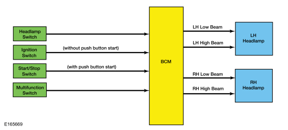
Low Beams
The BCM monitors the headlamp switch position by sending voltage signals on multiple circuits to the headlamp switch. There is one circuit for each headlamp switch position. At any given time, one of the signal circuits is switched to ground to indicate the headlamp switch position.
If the BCM detects a fault from the headlamp switch, the BCM turns the parking lamps and headlamps on. This is normal behavior of the BCM design as a fault has been detected with the inputs from the headlamp switch.
High Beams
The BCM monitors the multifunction switch for a high beam request. When the multifunction switch is in the high beam position, the low beams remain powered and the high beams are activated. This adds light and changes the headlamp beam pattern to illuminate a greater distance.
Flash-To-Pass
The BCM monitors the multifunction switch for a flash-to-pass request position. When the ignition is in RUN and the multifunction switch is in the flash-to-pass position, the high beams illuminate and remain illuminated until the multifunction switch is released.
Headlamp Exit Delay
When the ignition is OFF and the multifunction switch is placed in the flash-to-pass position and released, the parking lamps and low beams are illuminated. They remain illuminated until:
Within the 30 second delay and all the doors closed, opening any door results in the 3 minute timer restarting.
Daytime Running Lamps (DRL)
System Diagram
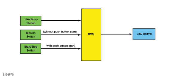
Daytime Running Lamps (DRL)
The DRL system utilizes the existing circuitry and components from low beams headlamps.
The BCM monitors the ignition status, the headlamp switch and autolamp status.
Based on the input, the BCM activates the DRL .
The DRL are activated when the ignition is in RUN and the low beams have not been turned on by the autolamp system or the headlamp switch.
The DRL feature is not a programmable parameter for this vehicle.
Autolamps
System Diagram
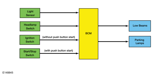
Autolamps
The BCM monitors the light sensor with a voltage signal. The light sensor input to the BCM varies with the ambient light conditions.
The headlamp switch sends a grounded input to the BCM to indicate the headlamp switch status (position or a fault within the headlamp switch).
When the BCM receives a headlamp switch status from the headlamp switch indicating a request for the autolamps, the BCM monitors the light sensor for the ambient light condition. If the BCM determines the ambient light level is dark, the BCM supplies voltage to the exterior lamps.
Headlamps On With Wipers On Function
When the headlamp switch is in the autolamps on position, the exterior lamps turn on when the front wipers are on. This feature does not activate the exterior lamps during a mist wipe or while the wipers are on to clear washer fluid during a wash condition.
The exterior lamps turn off when the ignition switches OFF or to ACC mode, the headlamp switch is placed in the off position, or the front wipers are turned off. The exception to this is when the exterior lights are on because of darkness determined by the autolamp system.
Stoplamps
System Diagram
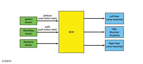
Stoplamps
The BCM monitors the input from the stoplamp switch. When the brake pedal is applied, voltage is routed to the BCM , indicating a request for the stoplamps. The BCM then supplies voltage to the stoplamps.
The BCM does not activate the stoplamps when the ignition is in OFF or ACC.
Turn Signal and Hazard Lamps
System Diagram
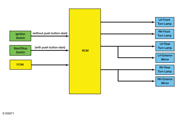
Turn Signals
The BCM monitors the multifunction switch position. When the multifunction switch is in the left or right turn position (second detent down or up), the BCM supplies on/off voltage to the appropriate turn lamps.
The timed on/off cycle for turn lamps is determined by the BCM and is set to flash approximately 75 times per minute if both the front and rear turn signal lamps operate correctly. If a front or rear turn signal lamp is inoperative, the BCM fast flashes the remaining turn lamp(s) approximately 150 times per minute to indicate a bulb outage to the driver.
When the multifunction switch is placed in the left or right lane change position (first detent down or up) and released, the turn signals flash 1 or 3 times (default is 3). This setting is programmed by the driver from the center display ( FCDIM ) in the instrument panel.
Hazard Lamps
The BCM sends a voltage signal to the hazard flasher lamp switch (integrated into the FCIM ) to monitor for a hazard lamp function request. When the hazard flasher lamp switch is pressed, the voltage signal is routed to ground, indicating a request to activate or deactivate the hazard lamp function.
When the BCM receives a request for the hazard lamps, the BCM supplies on/off voltage to all the turn lamps.
The timed on/off cycle for the hazard lamps is approximately 75 times per minute, regardless of bulb outage.
Parking, Rear, and License Plate Lamps
System Diagram
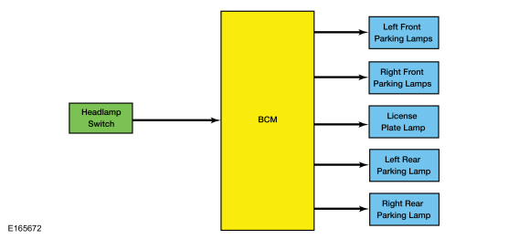
Parking Lamps
The BCM monitors the headlamp switch position by sending voltage signals on multiple circuits to the headlamp switch. There is one circuit for each headlamp switch position. At any given time, one of the signal circuits is switched to ground to indicate the headlamp switch position.
If the BCM detects a fault from the headlamp switch the it turns the parking lamps and headlamps on. This is normal behavior of the BCM design as a fault has been detected with the inputs from the headlamp switch.
When the BCM receives an input requesting the parking lamps on, it provides voltage to the parking and license plate lamps.
Fog Lamps
System Diagram
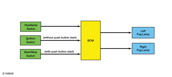
Fog Lamps
The BCM monitors the headlamp switch position by sending voltage signals on multiple circuits to the headlamp switch. There is one circuit for each headlamp switch position. At any given time, one of the signal circuits is switched to ground to indicate the headlamp switch position.
When the BCM receives a fog lamp input request from the headlamp switch, it provides ground to the fog lamp relay coil (located in the BJB ). When the fog lamp relay is energized, voltage is routed to the fog lamps.
Reversing Lamps
System Diagram
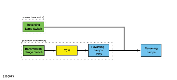
Reversing Lamps
When the transmission is placed in REVERSE with the ignition in RUN, the reversing lamp relay (automatic transmission) or the reversing lamp switch (manual transmission) provides voltage to the reversing lamps. The reversing lamps are located within the rear lamp assemblies.
Component Description
Headlamp Assembly
Exterior lamps are vented to accommodate normal changes in pressure. Condensation can be a natural by-product of this design. When moist air enters the lamp assembly through the vents, condensation can occur when the temperature is cold. When normal condensation occurs, a thin mist forms on the interior of the lens. The thin mist eventually clears and exits through the vents during normal operation. The amount of time it takes to clear the lens of acceptable mist varies with ambient humidity and lamp types. Normal condensation clears from any lamp in 48 hours under dry conditions.
Do not replace a lamp assembly with acceptable levels of condensation such as the presence of thin mist (no streaks, drip marks or droplets are present) or a fine mist covers less than 50% of the lens.
Examples of unacceptable moisture (usually caused by a lamp housing leak) are water puddling inside the lamp or large water droplets, drip marks or streaks present on the interior of the lens.
Headlamp Switch
The headlamp switch is hardwired to the BCM and ground. Depending on the switch position, one of up to 4 BCM input circuits are grounded. The fog lamp switch is integral to the headlamp switch.
Light Sensor
The BCM sends a voltage signal to the light sensor. The light sensor provides resistance between the voltage signal and ground. The resistance varies depending on the amount of ambient light detected by the light sensor. The brighter the ambient light, the lower the resistance. By the varying sensor resistance, the BCM determines the amount of ambient light.
Stoplamp Switch
The stoplamp switch is a normally open switch and is provided voltage at all times. When the brake pedal is applied, the switch closes and routes voltage to the BCM .
Copyright © Ford Motor Company