| 413-00 Instrument Panel Cluster (IPC) and Panel Illumination | 2014 Fiesta |
| Description and Operation | Procedure revision date: 05/21/2013 |
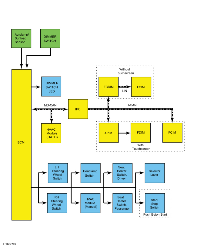
System Operation
System Diagram
Network Message Chart
IPC Network Input Messages
| Broadcast Message | Originating Module | Message Purpose |
|---|---|---|
| Illumination dimming level | BCM | Used to communicate the desired illumination level based on input from the dimmer switch. |
APIM , FCIM and FCDIM Network Input Messages
| Broadcast Message | Originating Module | Message Purpose |
|---|---|---|
| Illumination dimming level | IPC | Used to command illumination level of the Infotainment Controller Area Network (I-CAN) modules. |
HVAC Module ( EATC ) Network Input Messages
| Broadcast Message | Originating Module | Message Purpose |
|---|---|---|
| Illumination dimming level | BCM | Used to command the illumination level of the HVAC module. |
Dimmable Backlighting
The dimmable backlighting is controlled by the BCM based on the ambient light level and the illumination dimmer position. When the headlamps or parking lamps are on, the BCM monitors the non-networked input from the instrument panel dimmer switch and sends a pulse-width modulated voltage to the non-networked dimmable switches and components on two circuits. The BCM supplies and controls the start/stop switch backlighting illumination on a non-network circuit independent from the other non-network dimmable components. If a fault is detected by the BCM on a dimmable illumination output circuit, the BCM sets a DTC and disables the circuit function until the fault is cleared and an ignition cycle takes place.
The BCM also sends a message over the MS-CAN to the HVAC ( EATC ) and to the IPC to control the backlighting intensity level. The IPC sends the illumination dimming level message to the APIM , FCIM (touchscreen only) and FCDIM on the Infotainment Controller Area Network (I-CAN) based on the input received from the BCM over the MS-CAN . The receiving modules use the illumination dimming level message to determine the backlighting intensity of integral illumination sources. If the receiving module does not receive the backlighting status message from the BCM or from the IPC or if the data received is deemed invalid for more than 5 seconds, the receiving module sets a missing message related DTC in continuous memory and defaults the backlighting to full nighttime intensity.
When the headlamps or parking lamps are off and the sunload sensor detects daytime conditions, the IPC , the FCDIM and the FDIM are illuminated to full brightness.
If the exterior lamps are activated during the daytime on vehicles equipped with autolamps, the message center illumination remains at full intensity and does not dim from the instrument panel dimmer switch during this condition. If the vehicle travels under a bridge or through a tunnel, the low level of ambient light causes the illumination level of the message center to change to the level set by the instrument panel dimmer switch. The message center illumination changes back to full intensity when the intense ambient light is restored.
If the IPC does not receive the input signals of dimming level for up to 5 seconds, the last valid received state of these signals is assumed. If the IPC receives invalid or no signals for more than 5 seconds, it assumes full night illumination level.
On vehicles not equipped with a touchscreen, the FCDIM forwards the illumination dimming level message to the FCIM via the LIN circuit.
On vehicles equipped with a touchscreen, the APIM sends the illumination dimming level message to the FDIM .
On any audio system, if the sunload sensor detects nighttime conditions and the parking lamps or headlamps are on, only the ON/OFF volume button and the hazard/door lock switch are illuminated on the FCIM until the audio unit is turned on. If the audio unit is on while the ignition is in the OFF position and the parking lamps or headlamps are off but the sunload sensor detects nighttime conditions, it is possible to control the dimming level of the FCDIM , FCIM and FDIM .
Non-Dimmable Backlighting
When the ignition relay (located in the CJB ) is energized, switched voltage is supplied to the window control switches.
Field-Effect Transistor (FET) Protection
Field-Effect Transistor (FET) protection protects the BCM output drivers from damage in the event that an excessive current draw is detected on a BCM output.
For a full description of Field-Effect Transistor (FET) protection,
Refer to:
Module Controlled Functions - System Operation and Component Description
(419-10 Multifunction Electronic Modules, Description and Operation).
Component Description
Dimmer Switch
The instrument panel dimmer switch is a single detent rocker style switch with 2 inputs to the BCM to control all dimmable interior illuminated components. When the instrument panel dimmer switch is pressed up to increase the dimmable backlighting intensity or down to decrease the dimmable backlighting intensity, a ground signal is routed to the BCM . Based on the ground signal input from the instrument panel dimmer switch, the BCM sends a message over the network to the modules with dimmable backlighting, indicating the backlighting intensity level, and provides voltage to the non-networked dimmable illumination sources.
Copyright © Ford Motor Company