|
Vehicle drifts/pulls
|
Unevenly loaded or overloaded vehicle
|
GO to Pinpoint Test A
|
|
Tires/tire pressure
|
|
Alignment is not within specification
|
|
Brake drag
|
|
Steering components
|
|
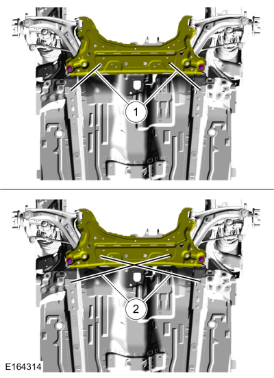
Subframe misalignment
|
|
Wander
|
Overloaded, unevenly or incorrectly loaded vehicle
|
NOTIFY the customer of incorrect vehicle loading.
|
|
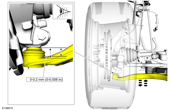
Ball joint(s)
|
INSPECT the ball joints. REFER to the Ball Joint Inspection component test in this section.
|
|
Damaged or missing front strut mount bearing(s)
|
INSTALL a new front strut mount bearing(s) as necessary.
REFER to:
Front Strut and Spring Assembly
(204-01 Front Suspension, Disassembly and Assembly).
|
|
Loose, worn or damaged front wheel bearing(s)
|
INSPECT the wheel bearings. INSTALL new wheel bearings as necessary.
REFER to:
Front Wheel Bearing
(204-01 Front Suspension, Removal and Installation).
|
|
Loose, worn or damaged suspension component(s)
|
INSTALL new suspension component(s) as necessary. Refer to the appropriate section in Group 204 for the procedure.
|
|
Loose suspension fasteners
|
INSPECT the suspension fasteners. TIGHTEN to specification. Refer to the appropriate section in Group 204 for the procedure.
|
|
Steering components
|
INSPECT the steering system. INSTALL new components as necessary. Refer to the appropriate section in Group 211 for the procedure.
|
|
Wheel alignment (excessive total front toe out)
|
ADJUST as necessary.
REFER to:
Front Toe Adjustment
(204-00 Suspension System - General Information, General Procedures).
|
|
Front bottoming or riding low
|
Worn, damaged or incorrect springs
|
MEASURE the ride height.
REFER to:
Ride Height Measurement
(204-00 Suspension System - General Information, General Procedures).
INSTALL new springs as necessary. REFER to:
Front Strut and Spring Assembly
(204-01 Front Suspension, Disassembly and Assembly).
|
|
Worn front strut(s)
|
INSTALL new struts as necessary.
REFER to:
Front Strut and Spring Assembly
(204-01 Front Suspension, Removal and Installation).
|
|
Abnormal/incorrect tire wear
|
Incorrect tire pressure (rapid center rib or inner and outer edge wear)
|
ADJUST the tire pressure. REFER to the
label. REFER to Diagnosis and Testing for further tire wear diagnosis.
|
|
Incorrect tire rotation intervals
|
Refer to the appropriate section in Group 103 for the procedure.
|
-
High-speed cornering
-
Excessive front or rear toe (inner or outer edge wear)
-
Excessive negative or positive camber (inner or outer edge wear)
|
REFER to:
Wheels and Tires
(204-04A Wheels and Tires, Diagnosis and Testing).
for further tire wear diagnosis.
|
|
Front or rear suspension components
|
INSPECT the front and rear suspension system. REPAIR or INSTALL new suspension components as necessary. Refer to the appropriate section in Group 204 for the procedure.
|
|
Sticky steering, poor returnability
|
Damaged or worn front strut mount bearing(s)
|
INSTALL a new front strut mount bearing(s) as necessary.
REFER to:
Front Strut and Spring Assembly
(204-01 Front Suspension, Disassembly and Assembly).
|
|
Binding ball joints
|
REFER to the Ball Joint Inspection component test in this section.
|
|
Steering components
|
INSPECT the steering system. INSTALL new components as necessary. Refer to the appropriate section in Group 211 for the procedure.
|
|
Steering wheel off-center
|
Unequal front or rear toe setting (side-to-side)
|
CHECK the wheel alignment.
REFER to:
Front Toe Adjustment
(204-00 Suspension System - General Information, General Procedures).
ADJUST as necessary.
|
|
Steering components
|
INSPECT the steering system. INSTALL new components as necessary. Refer to the appropriate section in Group 211 for the procedure.
|
|
Sway or roll
|
Overloaded, unevenly or incorrectly loaded vehicle
|
NOTIFY the customer of incorrect vehicle loading.
|
|
Loose wheel nut(s)
|
TIGHTEN the wheel nut(s) to specification.
REFER to:
Specifications
(204-04A Wheels and Tires, Specifications).
|
|
Strut(s) or shock absorber(s)
|
INSTALL new struts or shock absorbers as necessary.
REFER to:
Front Strut and Spring Assembly
(204-01 Front Suspension, Removal and Installation).
or REFER to:
Rear Shock Absorber
(204-02 Rear Suspension, Removal and Installation).
|
|
Loose stabilizer bracket-to-frame bolts
|
TIGHTEN the bolts to specification. Refer to the appropriate section in Group 204 for the procedure.
|
|
Worn stabilizer bar bushings or links
|
INSTALL new stabilizer bar bushings or links as necessary.
REFER to:
Front Stabilizer Bar Bushing
(204-01 Front Suspension, Removal and Installation).
|
|
Damaged or broken stabilizer bar
|
INSTALL a new stabilizer bar as necessary.
REFER to:
Front Stabilizer Bar
(204-01 Front Suspension, Removal and Installation).
|
|
Worn spring(s)
|
INSTALL new springs as necessary.
REFER to:
Front Strut and Spring Assembly
(204-01 Front Suspension, Disassembly and Assembly).
orREFER to:
Spring
(204-02 Rear Suspension, Removal and Installation).
|
|
Vehicle leans to one side
|
Unevenly loaded or overloaded vehicle
|
NOTIFY the customer of incorrect vehicle loading.
|
|
Front or rear suspension components
|
INSPECT the front and rear suspension systems. INSTALL new suspension components as necessary. Refer to the appropriate section in Group 204 for the procedure.
|
|
Incorrect drive axle(s) ride height. Side-to-side lean out of specification
|
MEASURE the ride height.
REFER to:
Ride Height Measurement
(204-00 Suspension System - General Information, General Procedures).
INSPECT the front and rear suspension systems. REPAIR or INSTALL new components as necessary. Refer to the appropriate section in Group 204 for the procedure.
|