| 412-00 Climate Control System - General Information | 2014 Fiesta |
| Description and Operation | Procedure revision date: 05/16/2013 |
System Diagram
System Diagram
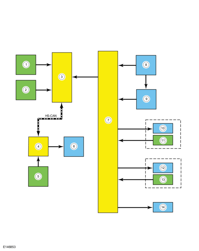
| Item | Description |
|---|---|
| 1 | Evaporator temperature sensor |
| 2 | Ambient air temperature sensor |
| 3 | IPC |
| 4 | PCM |
| 5 | A/C pressure transducer |
| 6 | A/C compressor clutch |
| 7 | HVAC control module |
| 8 | Blower motor |
| 9 | Blower motor resistor |
| 10 | Air distribution door actuator motor |
| 11 | Air distribution door actuator position sensor |
| 12 | Temperature door actuator motor |
| 13 | Temperature door actuator position sensor |
| 14 | Air inlet door actuator motor |
System Operation
Network Message Chart
Module Network Input Messages — Powertrain Control Module (PCM)
| Broadcast Message | Originating Module | Message Purpose |
|---|---|---|
| A/C request | IPC | This message requests the A/C compressor to be engaged. |
| Evaporator temperature | IPC | This message contains the evaporator temperature. The PCM uses the evaporator temperature to cycle the A/C compressor clutch. |
| Ambient air temperature | IPC | This message contains raw value from the Ambient Air Temperature (AAT) sensor. |
The Refrigerant Cycle
During A/C system shutdown, the refrigerant pressures are equal throughout the system. When the A/C compressor is in operation, it increases pressure on the refrigerant vapor, raising its temperature. The high-pressure and high-temperature vapor is then released into the top of the A/C condenser core.
The A/C condenser, being close to ambient temperature, causes the refrigerant vapor to condense into a liquid when heat is removed from the refrigerant by ambient air passing over the fins and tubing. The now liquid refrigerant, still at high pressure, exits from the bottom of the A/C condenser and enters the inlet side of the A/C receiver/drier. The receiver/drier is designed to remove moisture from the refrigerant.
The outlet of the receiver/drier is connected to the Thermostatic Expansion Valve (TXV). The Thermostatic Expansion Valve (TXV) provides the orifice, which is the restriction in the refrigerant system which separates the high and low pressure sides of the A/C system. As the liquid refrigerant passes across this restriction, its pressure and boiling point are reduced.
The liquid refrigerant is now at its lowest pressure and temperature. As it passes through the A/C evaporator, it absorbs heat from the airflow passing over the tube and fin sections of the A/C evaporator. This addition of heat causes the refrigerant to boil (convert to gas). The now cooler air can no longer support the same humidity level of the warmer air and this excess moisture condenses on the exterior of the evaporator tubes and fins and drains outside the vehicle.
The refrigerant cycle is repeated with the A/C compressor, increasing the pressure and temperature of the refrigerant.
The PCM controls the A/C clutch relay. The evaporator temperature sensor monitors the evaporator core discharge air temperature and sends a signal to the PCM . If the temperature of the evaporator core discharge air is low enough to cause the condensed water vapor to freeze, the A/C clutch is disengaged by the vehicle PCM .
The line pressure is monitored so that A/C compressor operation capacity may vary and may be interrupted if the system pressure becomes too high or too low.
The A/C compressor relief valve opens and vents refrigerant to relieve unusually high system pressure.
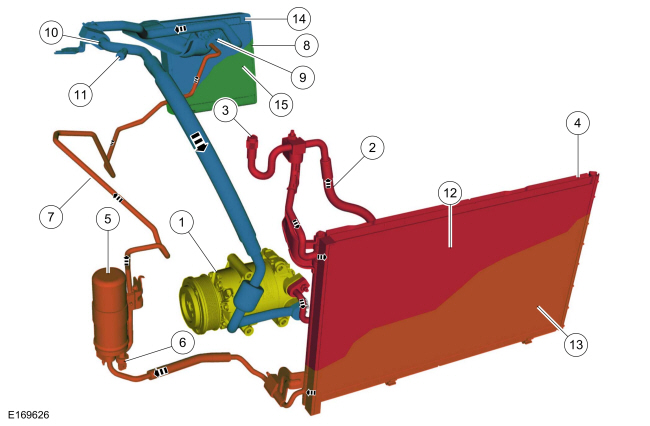
Thermostatic Expansion Valve (TXV) Type Refrigerant System-Gasoline Turbocharged Direct Injection (GTDI)
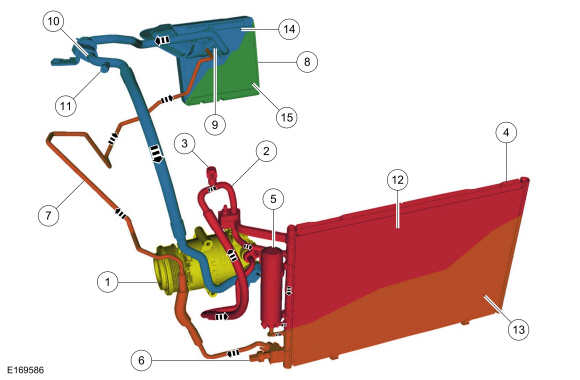
Thermostatic Expansion Valve (TXV) Type Refrigerant System-Twin Independent Variable Cam Timing (TiVCT)
Control System Logic
Controls and Compressor Operation
All customer requests for the Electronic Manual Temperature Control (EMTC) system come through the HVAC control module.
A/C (Air Conditioning) (if equipped) Request
The HVAC control module uses a dedicated wire to send the A/C request message to the IPC . The IPC sends the A/C request to the PCM through the HS-CAN .
When an A/C request is received by the PCM , the PCM engages the A/C clutch relay when:
Compressor Clutch
When A/C is requested and all conditions are within normal parameters, a ground is provided to the A/C clutch relay coil from the PCM , energizing the A/C clutch relay. When the PCM energizes the relay, voltage is supplied to the A/C compressor clutch field coil from the relay.
Sensor Inputs
The Ambient Air Temperature (AAT) sensor and the evaporator temperature sensor are inputs to the IPC . The A/C pressure transducer is an input to the PCM . If the temperatures are below a predetermined value, or the system pressure becomes too high or too low, the PCM does not allow the A/C compressor clutch to engage.
Heating and Ventilation
The heating and ventilation system:
Air Handling
All airflow from the blower motor passes through the evaporator core (if equipped). Based on the climate control system temperature
settings, the temperature door actuator directs airflow through the heater core as needed. The air distribution door actuator
controls the airflow to the defrost, footwell or register vents. The air source is from outside air or recirculated passenger
compartment air as determined by the air inlet door position. The cabin air filter is located in the heater core and evaporator
core housing. For cabin air filter maintenance intervals,
Refer to:
Maintenance Schedules - Gasoline Engines
(100-03 Maintenance Schedules, Description and Operation).
The air distribution door and temperature door actuators use a potentiometer to sense and communicate the door position to the HVAC control module. When in airflow mode or a desired temperature is requested by the HVAC control module, the appropriate door actuator motor is driven to the desired position, using the position sensed by the door actuator potentiometer to accurately position the door actuator.
The blower motor is controlled using a blower motor resistor. The blower motor resistor uses 3 resistors wired in series on the ground side of the blower motor. The blower motor has 4 speeds:
The HVAC control module grounds 1 of the 4 circuits to control the blower motor speed.
MAX A/C (if equipped)
When MAX A/C is selected:
PANEL
When PANEL mode is selected:
PANEL-FLOOR
When PANEL/FLOOR mode is selected:
OFF
When OFF is selected:
FLOOR
When FLOOR mode is selected:
FLOOR-DEFROST
When FLOOR/DEFROST mode is selected:
DEFROST
When DEFROST is selected:
Component Description
Component Description
Heating Ventilation Air Conditioning (HVAC) Control Module - Electronic Manual Temperature Control (EMTC)
The blower motor speed switch is mounted in the HVAC control module and controls blower motor speed by adding or bypassing resistors in the blower motor resistor in all modes except OFF. The blower motor speed switch is serviced only as an assembly with the HVAC control module.
The temperature control switch adjusts the discharge air temperature. Movement of the temperature knob from cool to warm causes a corresponding movement of the temperature door. The position of the temperature door determines the discharge air temperature. The temperature control selector is an integral part of the HVAC control module and cannot be serviced separately.
The airflow mode setting adjusts the discharge air outlet location. Each airflow mode selector icon causes a corresponding movement of the airflow mode doors and determines the discharge air outlet location. The airflow mode selector knob is an integral part of the HVAC control module and cannot be serviced separately.
The A/C button determines A/C compressor operation, except when the temperature selector is set to MAX A/C or the airflow mode selector is in defrost mode. The A/C button is an integral part of the HVAC control module and cannot be serviced separately.
The recirculated air request button can be activated in any mode except defrost. In MAX A/C mode the recirculated air indicator is illuminated (recirculated air forced on). The recirculated air request button is an integral part of the HVAC control module and cannot be serviced separately.
Electric Booster Heater
For information on the electric booster heater operation and diagnostics, refer to Section 412-02.
Blower Motor
The blower motor pulls air from the air inlet and forces it into the heater core and evaporator core housing and the plenum chamber where it is mixed and distributed.
Blower Motor Resistor
The blower motor resistor uses 3 resistance elements mounted on a resistor board to provide 4 blower motor speeds. Depending on the heater blower motor switch position, series resistors are added or bypassed in the blower motor resistor to decrease or increase blower motor speed.
Evaporator Core
The evaporator core is an aluminum tube and fin type and is located in the heater core and evaporator core housing. A mixture of liquid refrigerant and oil enters the bottom of the evaporator core through the evaporator core inlet tube and continues out of the evaporator core through the evaporator core outlet tube as a vapor. During A/C compressor operation, airflow from the blower motor is cooled and dehumidified as it flows through the evaporator core fins.
Heater Core
The heater core consists of fins and tubes arranged to extract heat from the engine coolant and transfer it to air passing through the heater core.
Heater Core and Evaporator Core Housing
The heater core and evaporator core housing directs airflow from the blower motor through the evaporator core and heater core. All airflow from the blower motor passes through the evaporator core. The airflow is then directed through or around the heater core by the temperature door. After passing through the heater core, the airflow is distributed to the selected outlet by the airflow mode doors.
Air Distribution Door Actuator
The air distribution door actuator contains a reversible electric motor and potentiometer. The potentiometer allows the HVAC control module to monitor the position of the airflow mode door. The HVAC control module drives the actuator motor in the direction necessary to move the airflow mode doors to the position set by the mode selector knob.
Air Inlet Door Actuator
The air inlet door actuator moves the air inlet door between the fresh and recirculated air positions on command from the HVAC control module. The air inlet mode door actuator is driven to, and automatically stops at, the full recirculated air or full fresh air inlet position and does not require a potentiometer circuit to monitor its position. The airflow mode door does not stop at any point between the recirculated air or fresh air inlet position.
Temperature Door Actuator
The temperature door actuator contains a reversible electric motor and potentiometer. The potentiometer allows the HVAC control module to monitor the position of the temperature door. The HVAC control module drives the temperature door actuator motor in the direction necessary to move the temperature door to the position set by the temperature selection knob.
Air Conditioning (A/C) Pressure Transducer
The PCM monitors the discharge pressure measured by the A/C pressure transducer. As the refrigerant pressure changes, the resistance of the A/C pressure transducer changes. It is not necessary to recover the refrigerant before removing the A/C pressure transducer.
A 5-volt reference voltage is supplied to the A/C pressure transducer from the PCM . The A/C pressure transducer receives a ground from the PCM . The A/C pressure transducer then sends a voltage to the PCM to indicate the A/C refrigerant pressure.
Ambient Air Temperature Sensor
The Ambient Air Temperature (AAT) sensor is an input to the IPC and is relayed to the PCM over the HS-CAN . The Ambient Air Temperature (AAT) sensor contains a thermistor. The sensor varies its resistance with the temperature. As the temperature rises, the resistance falls. As the temperature falls, the resistance rises.
Evaporator Temperature Sensor
The evaporator discharge air temperature sensor is an input to the IPC and is relayed to the PCM over the HS-CAN . An accurate evaporator temperature is critical for compressor engagement. The evaporator discharge air temperature sensor measures the temperature of the airflow immediately after the evaporator core. The evaporator temperature sensor contains a thermistor. The sensor varies its resistance with the temperature. As the temperature rises, the resistance falls. As the temperature falls, the resistance rises.
Air Conditioning (A/C) Compressor Clutch
When battery voltage is applied to the A/C compressor clutch field coil, the clutch plate and hub assembly is drawn toward the A/C clutch pulley. The magnetic force locks the clutch plate and hub assembly and the A/C clutch pulley together as one unit, causing the compressor shaft to rotate with the engine. When battery voltage is removed from the A/C compressor clutch field coil, springs in the clutch plate and hub assembly move the clutch plate away from the A/C clutch pulley.
An A/C clutch diode is integrated into the coil for A/C clutch field coil circuit spike suppression.
Internal Variable Displacement Air Conditioning (A/C) Compressor
NOTE: Variable compressors operate at lower pressures and are dependent on correct system charge for normal operation.
The internal variable displacement A/C compressor has:
Internal variable displacement A/C compressors are internally similar to fixed displacement compressors with a number of pistons placed around an angled plate that are pushed back and forth as the plate rotates. Internal variable displacement compressors vary the angle of the plate to allow piston displacement to be varied from 5% (default) to 100% of full capacity to meet cooling demand.
The displacement is controlled with an internal bellows actuated control valve which senses the intake low side (suction) pressure of the A/C refrigerant gas. The pressure varies with the temperature in the vehicle's cabin. The valve regulates the amount of refrigerant being discharged to maintain an optimum compressor displacement.
Thermostatic Expansion Valve (TXV)
The Thermostatic Expansion Valve (TXV) is located at the evaporator core inlet and outlet tubes at the center rear of the engine compartment. The Thermostatic Expansion Valve (TXV) provides a restriction to the flow of refrigerant and separates the low-pressure and high-pressure sides of the refrigerant system. Refrigerant entering and exiting the evaporator core passes through the Thermostatic Expansion Valve (TXV) through 2 separate flow paths. An internal temperature sensing bulb senses the temperature of the refrigerant flowing out of the evaporator core and adjusts an internal pin-type valve to meter the refrigerant flow into the evaporator core. The internal pin-type valve decreases the amount of refrigerant entering the evaporator core at lower temperatures and increases the amount of refrigerant entering the evaporator core at higher temperatures.
Air Conditioning (A/C) Condenser
The A/C condenser is an aluminum tube and fin design heat exchanger. It cools compressed refrigerant gas by allowing air to pass over tubes and fins to extract heat, and condenses gas to liquid refrigerant as it is cooled.
Receiver-Drier
The receiver/drier stores high-pressure liquid and the desiccant bag mounted inside the receiver/drier removes any retained moisture from the refrigerant.
Service Gauge Port Valves
The service gauge port fitting is an integral part of the refrigerant line or component.
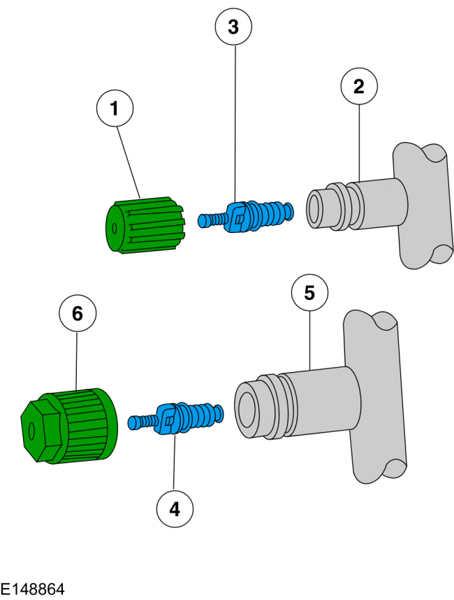
| Item | Torque | Description |
| 1 | 0.8 Nm (7 lb-in) | Low-pressure service gauge port valve cap |
| 2 | — | Low-pressure service gauge port valve |
| 3 | 2.26 Nm (20 lb-in) | Low-pressure Schrader-type valve |
| 4 | 3.4 Nm (30 lb-in) | High-pressure Schrader-type valve |
| 5 | — | High-pressure service gauge port valve |
| 6 | 0.8 Nm (7 lb-in) | High-pressure service gauge port valve cap |
Refrigerant System Dye
A fluorescent refrigerant system dye wafer is added to the receiver/drier desiccant bag to assist in refrigerant system leak diagnosis using a Rotunda-approved Ultra-violet (UV) blacklight. This fluorescent dye wafer dissolves after about 30 minutes of continuous A/C operation. It is not necessary to add additional dye to the refrigerant system before diagnosing leaks, even if a significant amount of refrigerant has been removed from the system.
Copyright © Ford Motor Company