| 307-01 Automatic Transmission - Vehicles With: 6-Speed PowerShift Transmission - DPS6/6DCT250 | 2014 Fiesta |
| Description and Operation | Procedure revision date: 05/16/2013 |
System Operation
General information
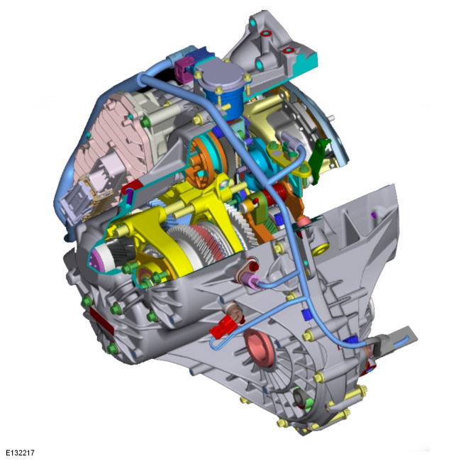
This DPS6/6DCT250 is a fully automatic, dry dual clutch, automatic shifting manual, electronically controlled 6-speed transaxle.
Its abbreviated designation DPS6 means:
In the parts catalog the DPS6 transmission may also be referred to as the PS195 transmission or the DCPS transmission.
The 6DCT250 is a dry dual clutch, automatic shifting manual transmission.
Its abbreviated designation 6DCT250 means:
This transaxle features the following:
This transaxle features two nested input shafts driven by a compact dry dual clutch system. These two shafts are used in conjunction with each other to provide seamless shifting through the six (6) available ratios with overdrive in the two top gears. As each gear is selected, the appropriate clutch is activated to drive the vehicle. Each consecutive gear is then preselected for the next “shift” operation as power is shifted from one clutch to the other and back again as moving up and down through the individual gears
This transaxle is designed to be operated in the same manner as a conventional torque converter equipped automatic transaxle. It provides the smooth application of power, but with the bonus of efficiencies found only in a manual transaxle. By delivering the power with a dual clutch system, fluid volume is limited to less than 2 liters as compared against a conventional automatic transaxle, and that is only within the gearbox case itself. The actuation of the clutch system is controlled by a dedicated computer through two individual electrically driven clutch motors and actuator systems.
If a fault occurs continued motoring is guaranteed in the following limited conditions based on the failure: 1st, 3rd and 5th gear if a fault with clutch 2 and/or relational components occurs. 2nd, 4th, 6th and reverse if a fault with clutch 1 and/or relational components occurs.
Internal components are based on manual transaxle technologies that include:
This transaxle is two transaxles within one housing that share a common:
The first consists of three odd gear ratios (1st, 3rd & 5th):
The second consists of three even gear ratios and reverse (2nd, 4th, 6th & Reverse):
The Select Shift ™ selector lever has the following positions:
If the selector lever is in the position P , then 1st gear and reverse gear are engaged via the TCM . This results in a faster response after the starting process.
Transmission design
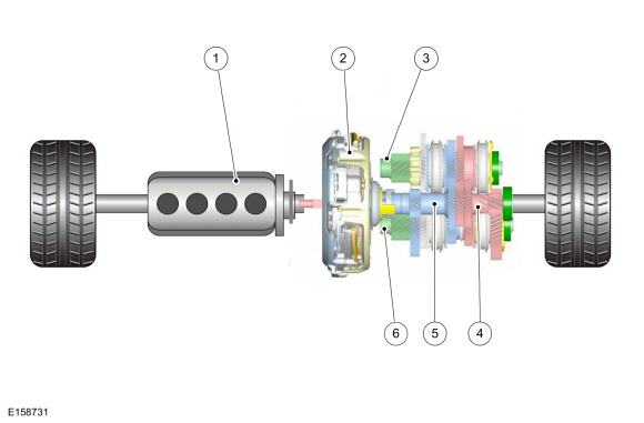
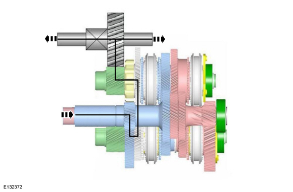
Schematic diagram
| Item | Description |
|---|---|
| 1 | Engine |
| 2 | Dry double clutch |
| 3 | Output shaft B - 3rd gear, 4th gear and reverse gear |
| 4 | Input shaft A - 1st gear, 3rd gear and 5th gear |
| 5 | Input shaft B - 2nd gear, 4th gear, 6th gear and reverse gear |
| 6 | Output shaft A - 1st gear, 2nd gear, 5th gear and 6th gear |
In principle, the transmission comprises two independent gear trains.
Each of the two input shafts is connected via outer splines to a clutch disc.
Each of the two output shafts provide a final drive gear ratio to the differential ring gear.
Input shaft A is the core shaft and drives the odd numbered gears (1st, 3rd, and 5th gear).
Input shaft B is the hollow shaft and drives the even numbered gears (2nd, 4th, and 6th gear) as well as the reverse gear (via an intermediate gear).
Output shaft A contains the driven gears and synchronizers for 1st, 2nd, 5th, and 6th gear as well as the intermediate gear for reverse.
Output shaft B contains the driven gears and synchronizers for 3rd, 4th, and reverse gears.
During driving, one gear train is always positively connected and the next gear is already engaged in the other gear train (although the clutch for this gear is still open).
Synchronizers
Single and double synchronization are both used on this transmission.
Single synchronization is used on gears 1, 3, 4, 5, 6 and reverse gear.
Double synchronization is used for the 2nd gear.
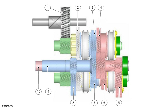
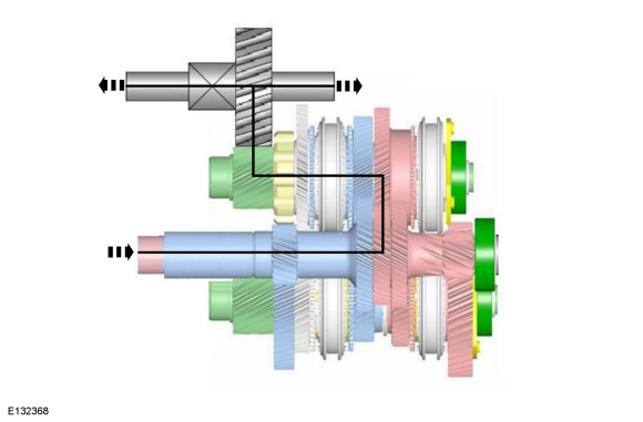
Torque Path
NOTE: In the descriptions below, the shafts are shown outside their actual position for greater clarity.
| Item | Description |
|---|---|
| 1 | Differential |
| 2 | Reverse gear |
| 3 | 4th gear |
| 4 | 3rd gear |
| 5 | 1st gear |
| 6 | 5th gear |
| 7 | 6th gear |
| 8 | 2nd gear |
| 9 | Input shaft B - 2nd gear, 4th gear, 6th gear and reverse gear |
| 10 | Input shaft A - 1st gear, 3rd gear and 5th gear |
First gear
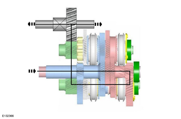
In first gear, engine torque flows from the flex plate to the flywheel and pressure plate A. Pressure plate A is engaged and torque is transferred to clutch disc A, which is on the engine side of the dual clutch assembly. From clutch disc A, torque flows to input shaft A (the inner, solid shaft). The small gear on the end of input shaft A transmits the torque to the first gear of output shaft A. In first gear, the 1-5 synchronizer on output shaft A engages first gear and allows torque to flow from the first gear to the output shaft. Torque is transmitted to the differential via the output shaft A pinion.
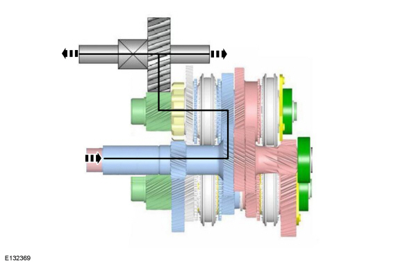
Second gear

In second gear, engine torque flows from the flex plate to the flywheel and pressure plate B. Pressure plate B is engaged and torque is transferred to clutch disc B, which is on the transmission side of the dual clutch assembly. From clutch disc B, torque flows to input shaft B (the outer, hollow shaft). The small gear near the middle of input shaft B transmits the torque to the second gear of output shaft A. In second gear, the 2-6 synchronizer on output shaft A engages second gear and allows torque to flow from the second gear to the output shaft. Torque is transmitted to the differential via the output shaft A pinion.
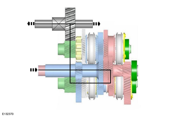
Third gear
In third gear, engine torque flows from the flex plate to the flywheel and pressure plate A. Pressure plate A is engaged and torque is transferred to clutch disc A. From clutch disc A, torque flows to input shaft A. The gear nearest the clutch on input shaft A transmits the torque to the third gear of output shaft B. In third gear, the third gear synchronizer on output shaft B engages third gear and allows torque to flow from the third gear to the output shaft. Torque is transmitted to the differential via the output shaft B pinion.
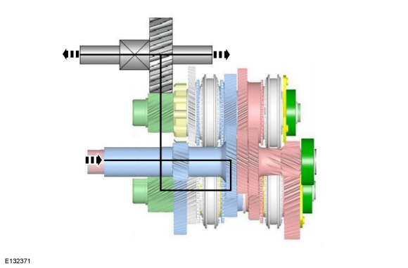
Fourth gear
In fourth gear, engine torque flows from the flex plate to the flywheel and pressure plate B. Pressure plate B is engaged and torque is transferred to clutch disc B. From clutch disc B, torque flows to input shaft B. The large gear on the end of input shaft B transmits the torque to the fourth gear of output shaft B. In fourth gear, the 4-R synchronizer on output shaft B engages fourth gear and allows torque to flow from the fourth gear to the output shaft. Torque is transmitted to the differential via the output shaft B pinion.
Fifth gear
In fifth gear, engine torque flows from the flex plate to the flywheel and pressure plate A. Pressure plate A is engaged and torque is transferred to clutch disc A. From clutch disc A, torque flows to input shaft A. The large gear on the end of input shaft A transmits the torque to the fifth gear of output shaft A. In fifth gear, the 1-5 synchronizer on output shaft A engages fifth gear and allows torque to flow from the fifth gear to the output shaft. Torque is transmitted to the differential via the output shaft A pinion.
Sixth gear
In sixth gear, engine torque flows from the flex plate to the flywheel and pressure plate B. Pressure plate B is engaged and torque is transferred to clutch disc B. From clutch disc B, torque flows to input shaft B. The large gear on the end of input shaft B transmits the torque to the sixth gear of output shaft A. In sixth gear, the 2-6 synchronizer on output shaft A engages sixth gear and allows torque to flow from the sixth gear to the output shaft. Torque is transmitted to the differential via the output shaft A pinion.
Reverse gear
In reverse gear, engine torque flows from the flex plate to the flywheel and pressure plate B. Pressure plate B is engaged and torque is transferred to clutch disc B. From clutch disc B, torque flows to input shaft B. The small gear in the middle of input shaft B transmits the torque to the second gear of output shaft A. The second gear has a fixed connection to the intermediate gear. The intermediate gear is in mesh with the reverse gear on output shaft B. In reverse gear, the 4-R synchronizer on output shaft B engages reverse gear and allows torque to flow from the reverse gear to the output shaft. Torque is transmitted to the differential via the output shaft B pinion.
Parking lock
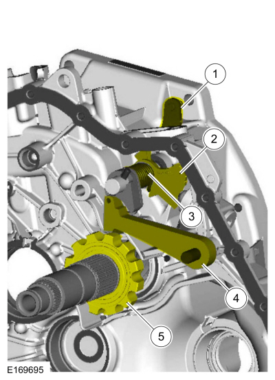
| Item | Description |
|---|---|
| 1 | Shift lever |
| 2 | Actuating shaft |
| 3 | Torsion spring |
| 4 | Park gear on output shaft B |
| 5 | Park pawl |
A park pawl needs to be installed since both clutches are opened after the engine is switched off.
Internal gearshift mechanism
Layout of the internal gearshift mechanism
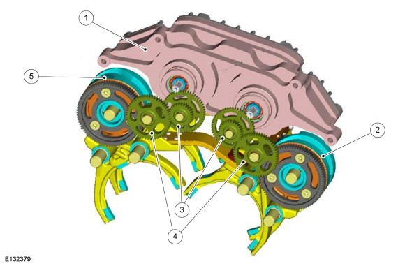
| Item | Description |
|---|---|
| 1 | Electric shift motors integrated in the TCM |
| 2 | Gear selector drum B with spur gear
Comments: Controls the selector forks for 2nd/6th gear and 4th/reverse gear |
| 3 | Double spur gear 1 |
| 4 | Double spur gear 2 |
| 5 | Gear selector drum A with spur gear
Comments: Controls the selector forks for 1st/5th gear as well as 3rd gear |
The gears are shifted by means of two brushless DC motors, which each actuate a gear selector drum via a two-stage transmission ratio. The gear selector drums each have one shift slot for moving the selector forks. As a result of using the gear selector drum principle, no additional mechanical lock is required in order to prevent more than one gear being engaged at the same time in the same sub-transmission in the event of a fault.
Layout of the gearshift system (schematic diagram)
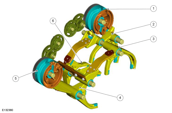
| Item | Description |
|---|---|
| 1 | Gear selector drum B with spur gear |
| 2 | Selector fork - reverse gear/4th gear |
| 3 | Selector fork - 3rd gear |
| 4 | Selector fork - 1st/5th gear |
| 5 | Gear selector drum A with spur gear |
| 6 | Selector fork - 2nd/6th gear |
Each gear selector drum actuates two selector forks. The total angle of rotation of the gear selector drums is limited by means of two stops which are cast as an integral part of the transmission housing.
The angle of rotation of the gear selector drum A is 200°. The angle of rotation of the gear selector drum B is greater and measures 290°, as this gear selector drum is used to shift four gears.
Overview of the gearshift system
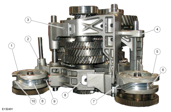
| Item | Description |
|---|---|
| 1 | Gear selector drum with spur gear |
| 2 | Selector fork - reverse gear/4th gear |
| 3 | Selector fork - 3rd gear |
| 4 | Selector fork - 1st/5th gear |
| 5 | Gear selector drum with spur gear |
| 6 | Shift slot |
| 7 | Lower cam |
| 8 | Selector fork - 2nd/6th gear |
| 9 | Sliding block |
| 10 | Upper cam |
The shift slot in the gear selector drum has two counter-running cams on its circumference, which are offset by 180°. A slider which is connected to the selector fork is moved via the shift slot. If the slider moves up or down on the cam then the selector fork is moved accordingly in an axial direction, and as a result either a gear is engaged or the synchronizer assembly is moved to the neutral position.
Function of the gear selector drum
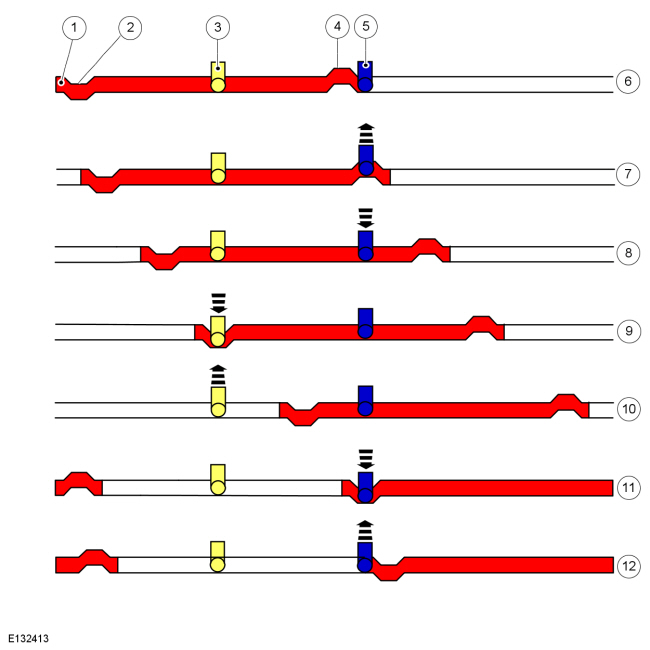
| Item | Description |
|---|---|
| 1 | Shift slot of gear selector drum A
Comments: In the colored area the angle of rotation is 200°. |
| 2 | Lower cam |
| 3 | Selector fork for 3rd gear with slider |
| 4 | Upper cam |
| 5 | Selector fork for 1st/5th gear with slider |
| 6 | Lower end position (rotation angle 0°) |
| 7 | Rotation angle 10°
Comments: The selector fork for 1st/5th gear is moved axially and 1st gear is engaged. |
| 8 | Rotation angle 55°
Comments: Neutral position between 1st gear and 3rd gear |
| 9 | Rotation angle 100°
Comments: The selector fork for 3rd gear is moved axially and 3rd gear is engaged. |
| 10 | Rotation angle 145°
Comments: Neutral position between 3rd gear and 5th gear |
| 11 | Rotation angle 190°
Comments: The selector fork for 1st/5th gear is moved axially and 5th gear is engaged. |
| 12 | Upper end position (rotation angle 200°) |
Function of the gear selector drum B
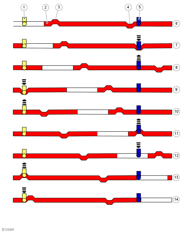
| Item | Description |
|---|---|
| 1 | Selector fork for 2nd/6th gear with slider |
| 2 | Shift slot of gear selector drum B
Comments: In the colored area the angle of rotation is 290°. |
| 3 | Upper cam |
| 4 | Lower cam |
| 5 | Selector fork for reverse/4th Gear with slider |
| 6 | Lower end position (rotation angle 0°) |
| 7 | Rotation angle 10°
Comments: Selector fork for reverse/4th gear is moved in an axial direction and reverse gear is engaged. |
| 8 | Rotation angle 55°
Comments: Neutral position between reverse gear and 2nd gear |
| 9 | Rotation angle 100°
Comments: The selector fork for 2nd/6th gear is moved axially and 2nd gear is engaged. |
| 10 | Rotation angle 145°
Comments: Neutral position between 2nd gear and 4th gear |
| 11 | Rotation angle 190°
Comments: Selector fork for reverse/4th gear is moved in an axial direction and 4th gear is engaged. |
| 12 | Rotation angle 235°
Comments: Neutral position between 4th gear and 6th gear |
| 13 | Rotation angle 280°
Comments: The selector fork for 2nd/6th gear is moved axially and 6th gear is engaged. |
| 14 | Upper end position (rotation angle 290°) |
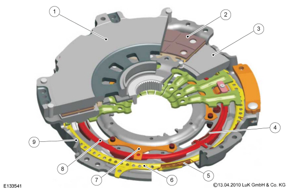
Double clutch system
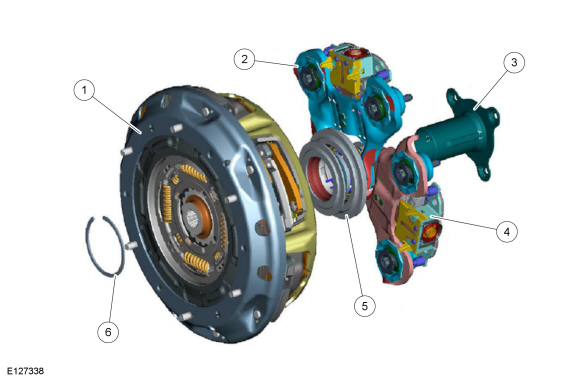
| Item | Description |
|---|---|
| 1 | Clutch unit |
| 2 | Clutch A actuator lever |
| 3 | Guide sleeve |
| 4 | Clutch B actuator lever |
| 5 | Engagement bearing |
| 6 | Snap ring |
The clutch system consists of:
The clutch unit is connected to the two input shafts of the transmission and attached to the drive plate with nuts. The nuts need to be removed from the drive plate if the transmission is removed.
Clutch unit
Sectional view
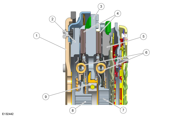
| Item | Description |
|---|---|
| 1 | Drive plate |
| 2 | Pressure Plate A - 1st gear, 3rd gear and 5th gear. |
| 3 | Driving disc |
| 4 | Clutch discs |
| 5 | Pressure Plate B - 2nd gear, 4th gear, 6th gear and reverse gear. |
| 6 | Torsion damper |
| 7 | Input shaft B hub |
| 8 | Input shaft A hub |
| 9 | Bearings of the driving disc |
The double clutch is designed to be open in the rest state. This type of clutch is referred to as an "active clutch". On an active clutch, the contact pressure is zero if no force or only a small force is applied at the lever springs.
The clutches are equipped with an internal travel-controlled wear adjustment system in order to keep the necessary actuator travel paths and therefore the required packaging space within tight limits.
Similar to many other dry clutch designs, torsional vibration dampers are integrated in the clutch discs.
The driving disc of the double clutch rides on a bearing that is pressed on the end of Input shaft B.
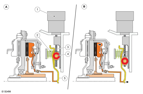
Schematic diagram of the open and closed clutch
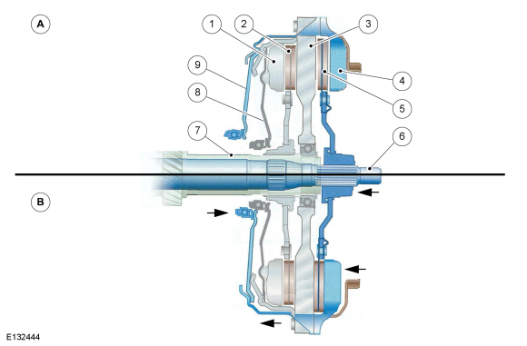
| Item | Description |
|---|---|
| A | Clutch in the rest state (open) |
| B | Clutch A closed |
| 1 | Pressure plate B |
| 2 | Clutch disc B |
| 3 | Driving disc |
| 4 | Pressure plate A |
| 5 | Clutch disc A |
| 6 | Input shaft A |
| 7 | Input shaft B |
| 8 | Lever spring B |
| 9 | Lever spring A |
The two lever springs open the clutches in the rest state. They are closed through actuation of the relevant engaging bearing, which acts on the corresponding lever spring. By pressing the lever springs, the relevant pressure plate is pressed against the clutch disc and the driving disc.
Engaging unit
Sectional view
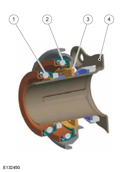
| Item | Description |
|---|---|
| 1 | Engaging bearing B
Comments: Actuates the lever spring B of clutch |
| 2 | Engaging bearing A
Comments: Actuates the lever spring A of clutch |
| 3 | Compensating element |
| 4 | Guide sleeve |
The two engaging bearings are accommodated by the guide sleeve in such a way that they can be moved independently of each other. The sliding sleeves are slotted for this purpose and engage in segments in each other. The compensating element is used to compensate for any offset to the actuating levers.
The two engaging bearings are each equipped with a hardened engaging disc. This lies loose on the engaging bearing and transmits the axial forces.
Electromechanical lever actuator
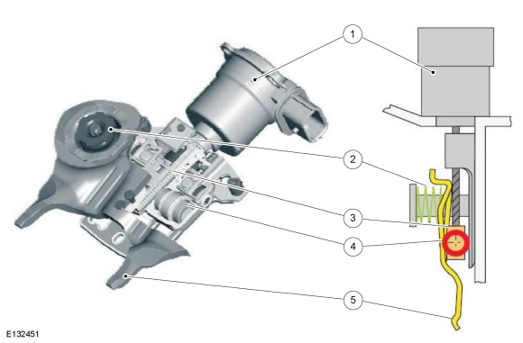
| Item | Description |
|---|---|
| 1 | Brushless DC clutch actuator motor |
| 2 | Pressure spring |
| 3 | Recirculating ball nut |
| 4 | Rollers |
| 5 | Engagement lever |
The force required to close the clutches is largely generated by a compression spring via the mechanical system of the lever actuator. This force acts on the outer end of the engaging lever. This has the form of a rocker. The rollers form the central point of contact of the engagement lever.
The brushless DC clutch actuator motors are bolted directly onto the transmission clutch housing. The DC clutch actuator motor drives the threaded bar of the ball screw via gear teeth. Through rotation of the threaded rod, the recirculating ball nuts and thus the rollers are moved in an axial direction.
Function of the electromechanical lever actuator
| Item | Description |
|---|---|
| A | Clutches open
Comments: Brushless DC clutch actuator motor de-energized |
| B | Clutch B closed
Comments: Brushless DC clutch actuator motor energized |
| 1 | Brushless DC clutch actuator motor |
| 2 | Pressure spring |
| 3 | Ball screw drive |
| 4 | Rollers |
| 5 | Engagement lever |
When the DC clutch actuator motor is de-energized the clutch is open. In order to close the clutch, the DC clutch actuator motor is actuated by the TCM . As a result of the rotation of the ball screw, the roller is moved downwards via the recirculating ball nut. Due to this axial movement of the rollers, the central support point of the engaging lever is displaced, as a result of which the leverage is altered. The change in leverage in turn causes the force which acts via the engaging lever and the engaging bearing on the lever spring of the clutch to be increased. The engaging bearing presses against the lever spring and the clutch is pressed into the closed position.
In order to hold the clutch in the closed position, a holding current is applied to the DC clutch actuator motor.
As soon as the holding current is switched off by the TCM , the lever springs will slacken and the clutch will open. Through the release of the lever springs, the engaging bearing and the engaging lever are rotated back. When the engaging lever is rotated back, the shape of the engaging lever ensures that the rollers return to their starting position.
TCM
Exploded view of the TCM
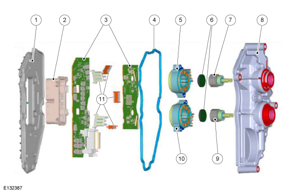
| Item | Description |
|---|---|
| 1 | Rear housing |
| 2 | Connection |
| 3 | Control unit |
| 4 | Gasket |
| 5 | B 2nd gear, 4th gear, 6th gear and reverse gear |
| 6 | Bearings of the electric motors |
| 7 | B 2nd gear, 4th gear, 6th gear and reverse gear |
| 8 | Front housing |
| 9 | A 1st gear, 3rd gear and 5th gear |
| 10 | A 1st gear, 3rd gear and 5th gear |
| 11 | Control unit connector plug |
The control unit and the two brushless DC shift motors for changing gears are integrated in the TCM . The primary function of the TCM is to collect the incoming signals from the sensors, evaluate these signals and control the actuators accordingly. In service, the TCM can only be replaced as a complete unit .
Control Strategies
Operating principle of the transmission.
In this transmission, the use of a dry double clutch in conjunction with an electromechanical control system means that two gears (transmission ratios) are engaged at the same time.
One of the clutches is engaged in driving mode, the other is already preselected when approaching the next gearshift with the clutch open.
Depending on the position of the accelerator pedal and the demand issued by the driver, the clutch of the previously activated gear is opened, while at the same time the clutch of the pre-selected gear is closed. As a result of this overlap in clutching, only minimal losses in tractive force are encountered during gearshifts.
Gearshift on a manual transmission
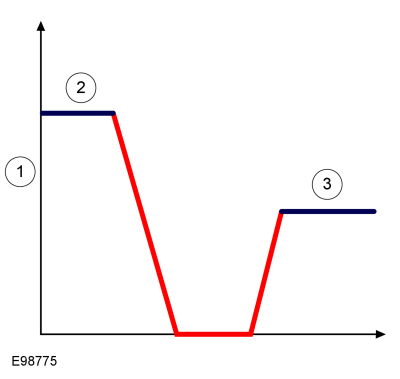
| Item | Description |
|---|---|
| 1 | Drive torque (Nm) |
| 2 | First gear |
| 3 | Second gear |
The illustration shows that in conventional manual transmissions, gearshifts result in a customary interruption of the propulsive force.
Gearshift process
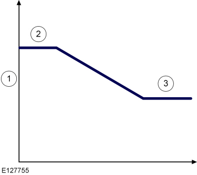
| Item | Description |
|---|---|
| 1 | Drive torque (Nm) |
| 2 | First gear |
| 3 | Second gear |
With this gearshift, shown under load in the illustration, the power flow is only slightly restricted; there is constant propulsion perceptible.
Control
The TCM controls the clutch and gearshift system with the aid of the four brushless DC motors with integrated position sensors.
The information about the position of the DC motors is sent to the TCM . On the basis of this information, the TCM knows which gears are engaged and which clutch the power flow is routed through.
Gearshift Control
The gearshift control system is based on a software strategy for shift point determination which corresponds to the driving conditions and the driver input.
The TCM actuates the relevant DC motors in order to perform the automatic gearshift.
In order to be able to precisely determine the shift points on the basis of the selected driving program, the TCM receives the following information:
Adaptive control
The TCM monitors each gearshift in order to enable smooth gearshifting under all driving conditions. To do this, the control unit controls the brushless DC motors for the clutch and gearshift system via an open-loop control system.
Adaptation of the following is performed:
The adapted values are stored in the non-volatile RAM (read/write memory) of the control unit. This permits improved shifting smoothness and increases transmission service life.
Automatic mode, selector lever in the D position
The TCM adapts the shift points to match the driving conditions.
If special driving conditions are detected, the TCM switches to predefined characteristics.
Select-shift mode
The Select-Shift mode can only be activated if the selector lever is in the S position. Individual gears can be requested by operating the Select-Shift switch which is located on the side of the selector lever. Manual gearshifting will only be performed if the engine speeds do not exceed 6500 RPM or fall below predetermined values.
Moving the selector lever from N to R
The TCM only permits shifting to reverse gear if the vehicle speed is less than 14.5 km/h.
At a vehicle speed above 14.5 km/h (10 mph), reverse gear is not engaged and the gearshift process is prevented.
Selector lever position N
In accordance with the calibration of the TCM , the following gears are engaged in the selector lever position N :
Selector lever position P
In accordance with the calibration of the TCM , 1st gear and reverse gear are engaged in the selector lever position P .
Altitude correction
Engine performance is reduced as air pressure decreases at higher altitudes. This situation is detected by the PCM .
In order to compensate for this operating situation, the TCM changes the shift points.
Speed control system
When the vehicle speed control system is switched on, a gear change can be executed by the TCM . This is done on the basis of the demand from the throttle plate position, which is controlled by the PCM .
Hill Start Assist
Hill start assist helps the driver when accelerating from a stop on an incline or side of a hill. Hill start assist supports the driver during drive-off situations on upward gradients. When the driver releases the vehicle brake, hill start assist prevents the vehicle from rolling back in the opposite direction.
Hot mode
The temperature of the clutch is calculated via a model in the TCM .
The following variables are incorporated in the calculation:
The Hot Mode function is used to prevent the clutch from being damaged as a result of excessively high temperatures. When hot mode is active, the clutch is engaged more quickly and the engine torque is reduced.
At a calculated clutch temperature at which the clutch lining would suffer heat damage, the following message is displayed on the message center:
Once the clutch has cooled down, the message "Transmission ready for operation" is displayed on the multi-function display of the instrument cluster.
At a calculated clutch temperature of more than 300 °C the clutches are disengaged.
Limp home mode
The TCM software contains functions which take control of the transmission if serious faults occur.
The fault characteristic decides which strategies are to be used.
The vehicle remains capable of restricted operation, unless there is a fault in the TCM itself or at the TR sensor.
NOTE: If the TR sensor is defective, both clutches are disengaged and it is no longer possible to continue driving. In the event of failure of the TR sensor, it is no longer possible to start the vehicle, or the transmission is fixed in the N position, as a result of which it is impossible to continue driving.
Different measures are implemented depending on the current gear position and driving situation when the fault occurs:
When the engine is started again (ignition switched off for approximately 15 seconds), a self-test is performed in order to check whether there are any faults in the system. If the fault is still present, limp home mode is reactivated. If the fault is no longer present then it is no longer displayed on the instrument cluster and the MIL and/or the transmission control light will be off. However, the fault remains stored in the TCM .
In the event of a fault, it is recommended to continue driving so long as it is necessary and to look for the nearest workshop or to park the vehicle in a safe location.
Component Description
Double clutch with travel-controlled wear adjustment
As a result of wear to the clutch discs, the positions of the lever springs change, and this in turn alters the characteristic curves of the contact pressure and disengaging force. The consequence of this would be increased loads on the brushless DC motors of the electromechanical lever actuators.
In order to keep the position of the lever springs and therefore the contact pressure and disengaging force more or less constant, the double clutch has a travel-controlled wear adjustment mechanism.
It comprises the following main components:
Sectional view of clutch B of the double clutch
| Item | Description |
|---|---|
| 1 | Driving disc |
| 2 | Clutch disc B |
| 3 | Pressure plate B |
| 4 | Adjustment roller spring |
| 5 | Adjustment tension spring |
| 6 | Adjustment ramp ring |
| 7 | Clamping spring |
| 8 | Ramp ring |
| 9 | Clutch cover |
The adjustment of the clutch is triggered if - as a result of wear to the clutch lining - the lever spring for generating a specific contact pressure is pressed through further in the direction towards the engine. As a result of the additional travel, the clamping spring lifts off the ramp ring. As a result of the pre-loaded adjustment roller spring, the ramp ring is rotated on the ramp until the clearance between the clamping spring and the ramp ring has been compensated for. If the clutch is then fully opened (i.e. disengaged) again as a result of a gearshift process, the lever spring moves into a new position due to the rotation of the ramp ring, and this creates an air gap between the lever spring and the adjustment ramp ring. As a result of the adjustment ramp ring, which is also spring-loaded, it is then rotated until it abuts against the lever spring. The adjustment process is then complete.
Flow chart
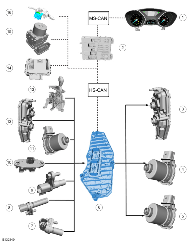
| Item | Description |
|---|---|
| 1 | Instrument Cluster |
| 2 | BCM |
| 3 | Electric shift motors in the
TCM
Comments: actuate the shift shafts |
| 4 | DC clutch actuator motor A |
| 5 | DC clutch actuator motor B |
| 6 | TCM |
| 7 |
ISS
sensor A
|
| 8 | ISS sensor B |
| 9 | OSS |
| 10 | The TR sensor |
| 11 | Hall sensors of the DC clutch actuator motor A and B |
| 12 | Hall sensors of the electric shift motors in the TCM |
| 13 | Select-shift switch |
| 14 | PCM |
| 15 | ABS |
| 16 | Steering wheel rotation sensor |
Function of the electronic components
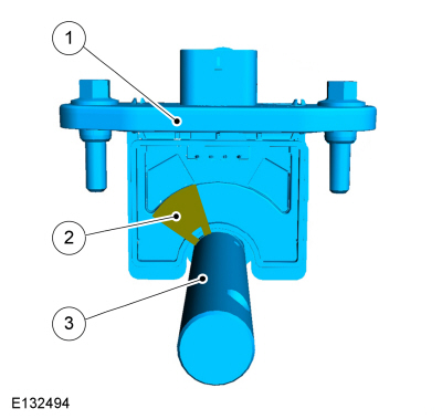
ISS sensor A 1st gear, 3rd gear and 5th gear
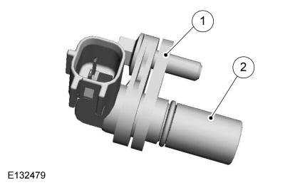
| Item | Description |
|---|---|
| 1 | Spacer |
| 2 | ISS sensor A |
The ISS sensor A is attached to the transmission housing. The spacer washer provides a defined distance between the sensor and the transmitter wheel. The spacer washer has a thickness of 3.5 mm ± 0.05 mm.
The sensor detects the rotational speed of 3rd gear on output shaft B. It is a magneto-resistive sensor which measures the rotational speed and the direction of rotation.
ISS sensor B 2nd gear, 4th gear, 6th gear and reverse gear
| Item | Description |
|---|---|
| 1 | Spacer |
| 2 | ISS sensor B |
The ISS sensor B is attached to the transmission housing. The spacer washer provides a defined distance between the sensor and the transmitter wheel. The spacer washer has a thickness of 3.2 mm ± 0.05 mm.
The sensor detects the rotational speed of 4th gear on output shaft B (hollow shaft). It is a magneto-resistive sensor which measures the rotational speed.
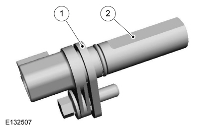
The OSS sensor
The OSS sensor is attached to the transmission housing.
The sensor detects the rotational speed via a transmitter wheel which is attached to the differential. It is a magneto-resistive sensor which measures the rotational speed.
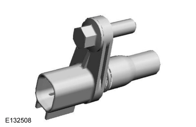
The TR sensor
| Item | Description |
|---|---|
| 1 | The TR sensor |
| 2 | Cover plate |
| 3 | Actuating rod |
The TR sensor detects the position of the manual control lever shaft. The TR sensor is mounted on the transaxle. The TR sensor allows the vehicle to start in PARK and NEUTRAL positions. The TR sensor output signal is linear over the measurement range and the TCM receives the selector lever position.
The signals of the TR sensor are used for the following functions:
No substitute signal is available for the TR sensor.
If the connection is cut, the vehicle cannot be started.
The TR sensor requires to be calibrated through the adaptive learning procedures.
Electric motors
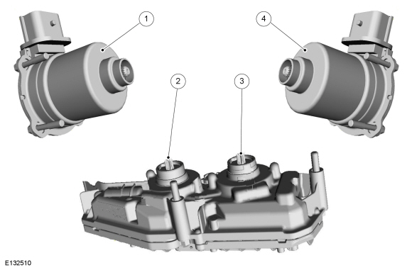
| Item | Description |
|---|---|
| 1 |
DC
clutch actuator motor A
Comments: Actuates the clutch for 1st, 3rd and 5th gear via the electromechanical lever actuator |
| 2 | Electric shift motor A in the
TCM
Comments: Controls the selector forks for 1st/5th gear and 3rd gear via the gear selector drum 1 |
| 3 | Electric shift motor B in the
TCM
Comments: Controls the selector forks for 2nd/6th gear and 4th/reverse gear via the gear selector drum 2 |
| 4 |
DC
clutch actuator motor B
Comments: Actuates the clutch for 2nd, 4th, 6th and reverse gear via the electromechanical lever actuator |
All electric motors are designed as brushless DC motors.
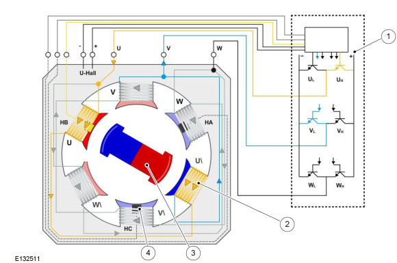
| Item | Description |
|---|---|
| 1 | Motor control in the TCM |
| 2 | Stator coils |
| 3 | Rotor |
| 4 | Hall sensor |
The stator coils are actuated by the electronics in the TCM in such a way that a circumferential magnetic field is generated. The rotor runs behind the magnetic field. Via the Hall sensors, the TCM receives information on the position of the rotor and calculates by how many rotations the motor has been turned. This information is required by the TCM to actuate the shift forks in accordance with the specified torque angle and to actuate the clutches.
Copyright © Ford Motor Company