
| 206-06 Hydraulic Brake Actuation | 2014 Fiesta |
| Removal and Installation | Procedure revision date: 03/7/2013 |
Removal
NOTICE: Do not service the brake pedal or brake booster without first removing the stoplamp switch and the cruise control deactivator switch. Remove the switches with the brake pedal in the at-rest position. The switch plunger must be compressed for the switch to rotate in the bracket. Removing the switches with the plunger extended (during pedal apply) will result in switch damage.
 WARNING:
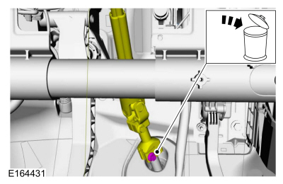
Do not reuse steering column shaft bolts. This may result in fastener failure and steering column shaft detachment or loss
of steering control. Failure to follow this instruction may result in serious injury to vehicle occupant(s).
WARNING:
Do not reuse steering column shaft bolts. This may result in fastener failure and steering column shaft detachment or loss
of steering control. Failure to follow this instruction may result in serious injury to vehicle occupant(s).
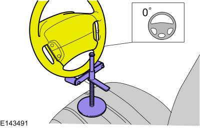
NOTICE: Do not allow the steering column to rotate while the steering column shaft is disconnected or damage to the clockspring may result. If there is evidence that the steering column shaft has rotated, remove and re-center the clockspring. Refer to Section 501-20B.
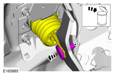
NOTE: The booster push rod clevis-locking pin is a one-time use only part. Any time the booster push rod clevis-locking pin is removed, a new booster push rod clevis-locking pin should be used.
Installation
NOTICE: Do not press, pull or otherwise move the brake pedal while installing the stoplamp switch and cruise control deactivator switch. Install these switches with the booster push rod attached to the brake pedal and with the brake pedal in the at-rest position. Installing these switches with the brake pedal in any other position will result in incorrect adjustment and may damage the switches.
To install, reverse the removal procedure.Copyright © Ford Motor Company