
| 307-01 Automatic Transmission - Vehicles With: 6-Speed PowerShift Transmission - DPS6/6DCT250 | 2014 Fiesta |
| Removal and Installation | Procedure revision date: 09/3/2013 |
Removal
NOTE: Note the position of the component before removal.
NOTE: Only tighten the bolt finger tight at this stage.
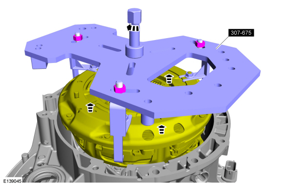
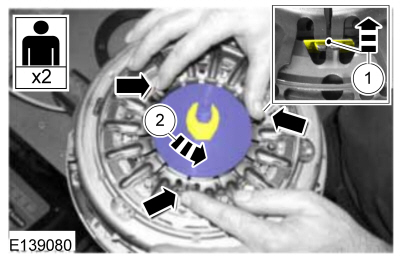
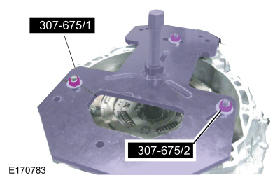
NOTICE: Make sure the lifting legs are installed on the clutch studs marked with the stamped manufacturing mark as shown.
NOTICE: Installing the lifting legs on unmarked clutch studs will damage the pressure plate adjuster.
NOTICE: Make sure the lifting leg with the angle is in the location shown.
Special Tool(s) : 307-675 Fixture, Clutch Remover/Installer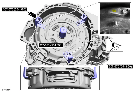
Installation
 A video version of this procedure is available on-line.

NOTICE: New clutches are shipped with the clutch locks locked. Attempting to reset a locked clutch will damage the clutch. Steps 4 through 16 only apply if the clutch is unlocked.
Verify clutch 2 locks are locked.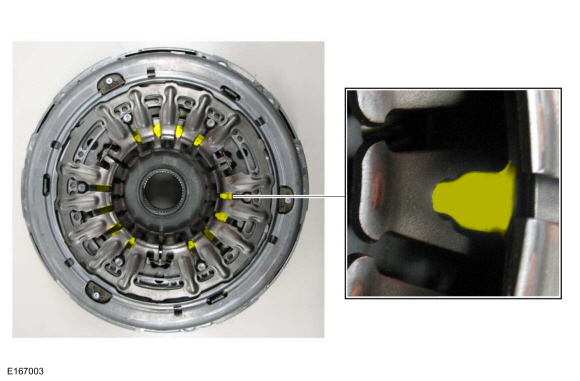
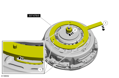
NOTE: Only tighten the nut and bolt finger tight at this stage.
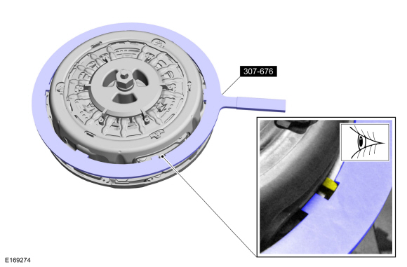
Special Tool(s) : 307-676 Tool, Clutch 1 and 2 Reset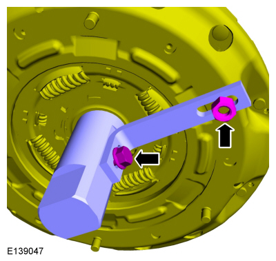
NOTE: Only tighten the nut and bolt finger tight at this stage.
Special Tool(s) : 307-676 Tool, Clutch 1 and 2 Reset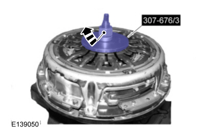
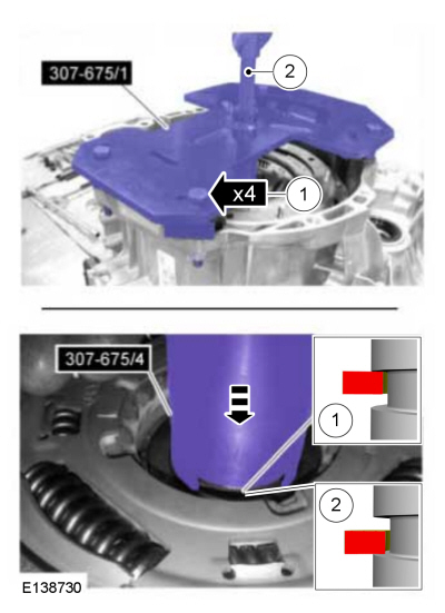
NOTICE: Failure to rotate the self-adjuster to the stops before compressing the clutch, causes damage to the clutch.
NOTE: Only tighten the nut finger tight at this stage.
Special Tool(s) : 307-676 Tool, Clutch 1 and 2 Reset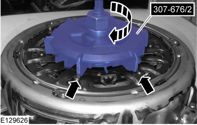
NOTICE: Failure to rotate the self-adjuster to the stops before compressing the clutch, causes damage to the clutch.
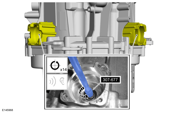
NOTE: An audible click can be heard when the clutch locks lock.
While holding the clutch self-adjuster to the stops, use the special tool and compress the clutch to the stops on the clutch. The locks on clutch 2 lock at this time.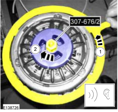
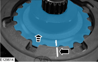
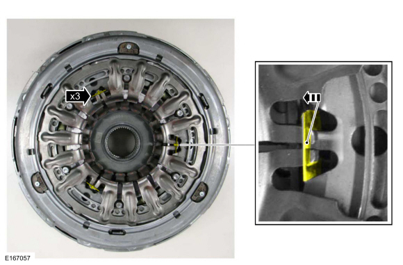
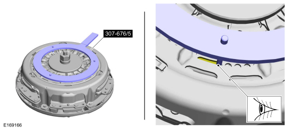
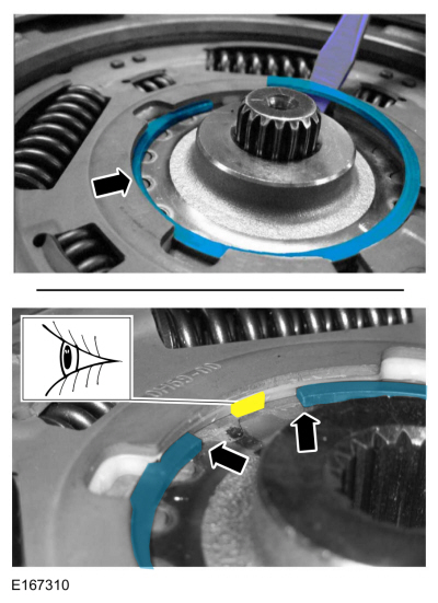
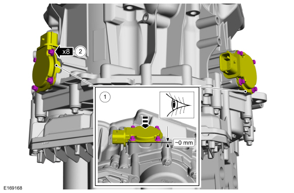
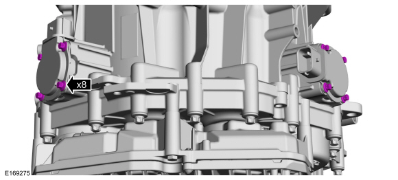
NOTE: The minimum number of engaged clutch locks is 6. Make sure the 6 locked clutch fingers align with the clutch studs as shown. If not, reset the clutch 2 locks as necessary.
NOTE: 4 locks shown, 12 total.
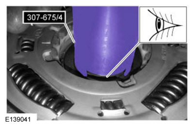
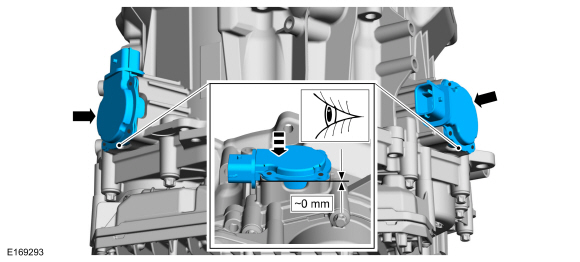
Visually check the locks to make sure they have locked.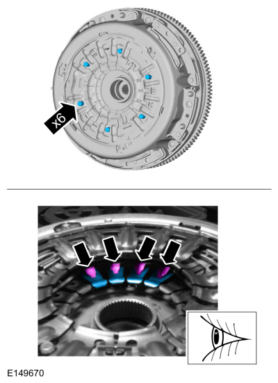
NOTE: This step does not need to be performed if a new clutch is being installed.
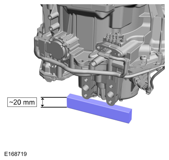
NOTE: Use a 0-75mm caliper.
Replace clutch if clearance is less than the specified value.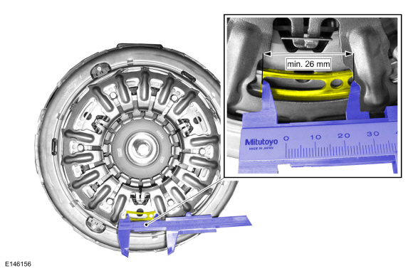
NOTE: This step does not need to be performed if a new clutch is being installed.
Replace clutch if clearance is less than the specified value.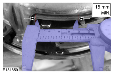
NOTICE: Do not tilt the transmission until after Step 28 when the clutch locks are released. Failure to do so may cause the Z-washers to fall out of place causing a noise issue or damage.
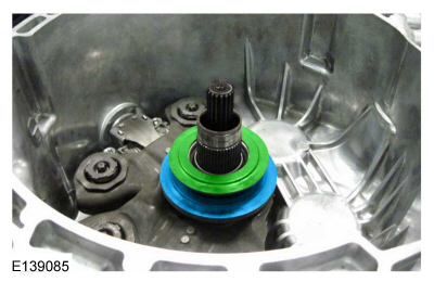
NOTE: The component can only be installed in 1 position.
NOTE: A small amount of adhesive is applied between the Z-washer and the bearing surface to aid factory assembly. This is NORMAL and not required in service during a repair.
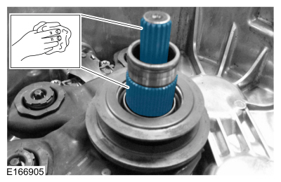
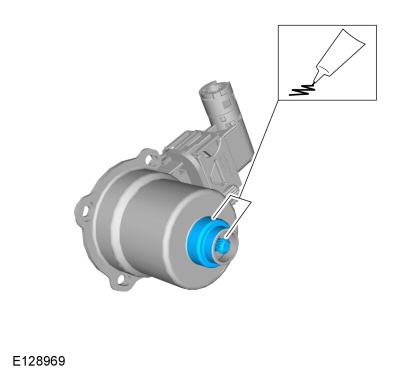
NOTICE: Excessive oil can contaminate the clutch. Only apply enough oil to lubricate the shaft for clutch installation.
Apply a thin coating.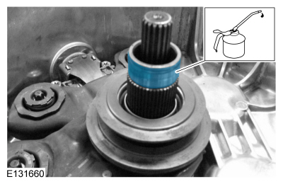
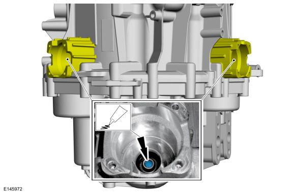
NOTICE: Excessive grease can contaminate the new clutch. Apply 1 gram or about 1/3 tube of the grease provided in the kit.
Apply a small amount of DPS6 Grease on both input shaft splines.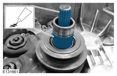
NOTICE: Do not tilt the transmission until after Step 26 when the clutch locks are released. Failure to do so may cause the Z-washers to fall out of place, causing a noise issue or damage.
NOTICE: Verify the clutch locks are locked prior to installation or the transaxle may not operate correctly and damage can occur. If the clutch locks are not locked go to step 4 within this procedure.
NOTICE:
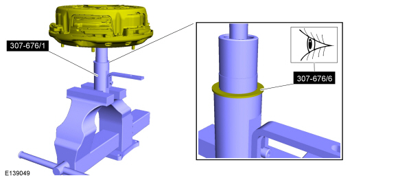
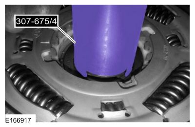
NOTE: The clutch splines are properly aligned when the end of the hollow input shaft is near the clutch bearing centerline.
Special Tool(s) : 307-675 Fixture, Clutch Remover/Installer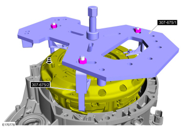
NOTICE: Do not overtighten the special tool or damage can occur.
Special Tool(s) : 307-675 Fixture, Clutch Remover/Installer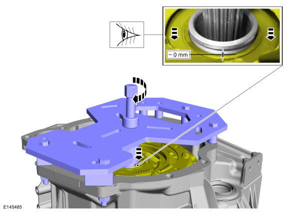
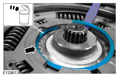
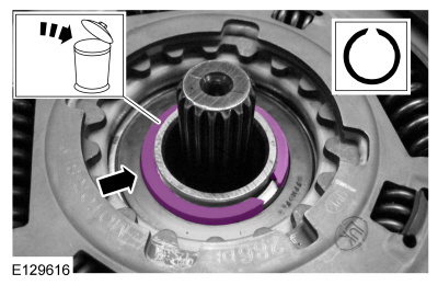
NOTE: Make sure that a new component is installed.
The snap ring ends are tapered for easier removal. Install the new snap ring with the narrow opening on top.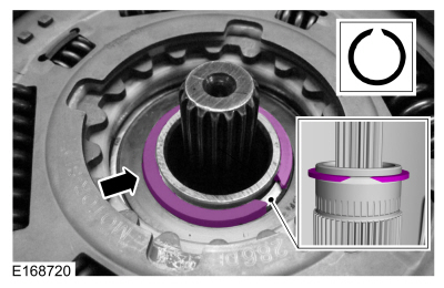
NOTE: Verify snap ring is secure in groove.
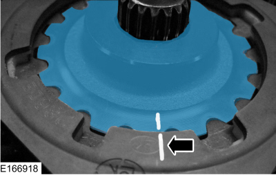
NOTE: Make sure the installation marks are aligned.
NOTE: Make sure that a new component is installed.
NOTE: The component can only be installed in 1 position.
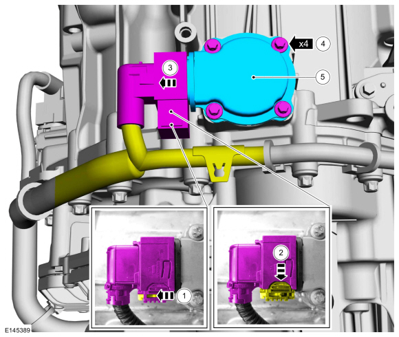
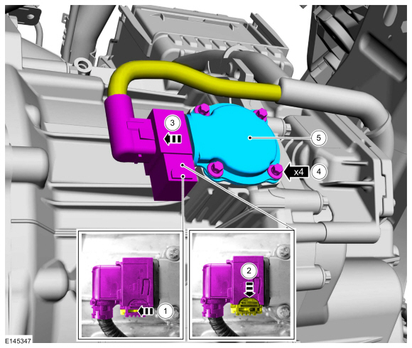
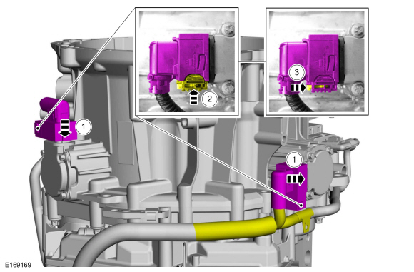
NOTICE: Use only hand pressure to align the splines and seat the motor. Do not use the bolts to draw the motor to the case. Forcing the motor into the case will damage the clutch motor and engagement lever.
NOTE: Clutch motor splines may need to be turned to ease installation.
Copyright © Ford Motor Company