| 413-01 Instrumentation, Message Center and Warning Chimes | 2014 Fiesta |
| Description and Operation | Procedure revision date: 05/21/2013 |
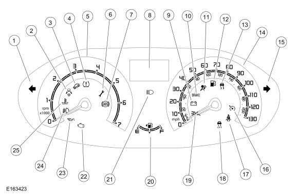
Overview
| Item | Description |
|---|---|
| 1 | Left turn signal indicator |
| 2 | Door ajar indicator |
| 3 | Grade assist indicator |
| 4 | TPMS warning indicator |
| 5 | Tachometer |
| 6 | Powertrain malfunction (wrench) indicator |
| 7 | ABS warning indicator |
| 8 | Integrated LCD |
| 9 | Charging system warning indicator |
| 10 | Brake warning indicator |
| 11 | Airbag warning indicator |
| 12 | Low fuel warning indicator |
| 13 | Stability-traction control (sliding car icon) indicator |
| 14 | Speedometer |
| 15 | Right turn signal indicator |
| 16 | Cruise control indicator |
| 17 | Safety belt warning indicator |
| 18 | Stability-traction control disabled (sliding car OFF icon) indicator |
| 19 | Lights on indicator |
| 20 | Fuel gauge |
| 21 | High beam indicator |
| 22 | MIL |
| 23 | Low oil pressure warning indicator |
| 24 | Front fog lamp indicator |
| 25 | Engine temperature warning indicator |
The IPC contains gauges, informational indicators, warning indicators and an integrated LCD designed to provide the driver with system status and to alert the driver when certain conditions exist in the vehicle.
Gauges
Gauges inform the driver of the status of systems. The systems that use gauges are as follows:
Informational and Warning Indicators
Informational indicators provide information to the driver of conditions that exist in the vehicle. Warning indicators provide information to the driver of conditions that could potentially cause personal injury or alter vehicle performance.
All informational and warning indicators are Light Emitting Diodes (LEDs) and are not replaced separate from the IPC .
IPC Integrated LCD
The IPC integrated LCD , located in the top center of the IPC , uses a 3-line LCD . The IPC integrated LCD is controlled by the trip computer switch, located on the multifunction switch. The IPC integrated LCD provides the following information:
Network Messaged Inputs
Module messaging has increased over time and has become the standard for sending and receiving information required to operate the IPC . The majority of the inputs required to operate the IPC are received over the CAN .
Hardwired Inputs
The IPC requires hardwired inputs from components that are not on the CAN . These components are required for specific IPC functions.
The hardwired inputs are provided by the following components:
Copyright © Ford Motor Company