| 308-01A Clutch - Vehicles With: 5-Speed Manual Transmission - B5/IB5 | 2014 Fiesta |
| Description and Operation | Procedure revision date: 04/25/2013 |
System Operation
How the clutch works
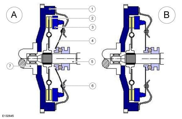
Cross-sectional view of a single disc dry clutch
| Item | Description |
|---|---|
| A | Clutch disengaged |
| B | Clutch engaged |
| 1 | Flywheel |
| 2 | Clutch disc |
| 3 | Pressure plate |
| 4 | Diaphragm spring |
| 5 | Transmission input shaft |
| 6 | Clutch cover |
| 7 | Crankshaft dimensions |
The clutch transmits engine torque from the engine to the transmission. When the clutch pedal is pressed the power from the engine to the transmission is interrupted.
When the clutch pedal is not pressed the clutch is engaged. Pressing the clutch pedal disengages the clutch.
A dry clutch usually only has one clutch disc, the coatings of which are specially designed for dry friction with a higher coefficient of friction. The torque which can be transmitted also depends on the size and number of friction surfaces and the pressing force.
The flywheel and pressure plate are connected to the crankshaft in a rotationally fixed way and transmit the torque via the friction linings of the clutch disc to the input shaft of the transmission. The clutch disc is clamped between the flywheel and the pressure plate. The force from the diaphragm spring provides the necessary contact pressure.
The clutch cover, pressure plate and diaphragm spring are also referred to as the clutch pressure plate.
The wear on the clutch disc is greatest at the pressure point during engagement of the clutch. If the pressure plate is moved away from the flywheel then there is no longer any friction to the clutch disc, and the connection is disengaged.
The most frequent damage observed on the clutch is too low friction (sliding) between the clutch disc and the pressure plate or flywheel. This can be caused by oil leaks, friction lining wear or a weakening diaphragm spring.
Torque Path
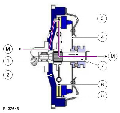
Torque path in a single disc dry clutch
| Item | Description |
|---|---|
| M | Ground torque path |
| 1 | Crankshaft dimensions |
| 2 | Flywheel |
| 3 | Clutch cover |
| 4 | Diaphragm spring |
| 5 | Pressure plate |
| 6 | Clutch disc with friction linings |
| 7 | Transmission input shaft |
The torque path in a single disc dry clutch as shown in the diagram above is as follows:
Component Description
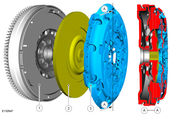
Components of a clutch
| Item | Description |
|---|---|
| 1 | Flywheel |
| 2 | Clutch disc |
| 3 | Clutch cover assembly |
| A | Sectional plane A |
Self-adjusting Clutch
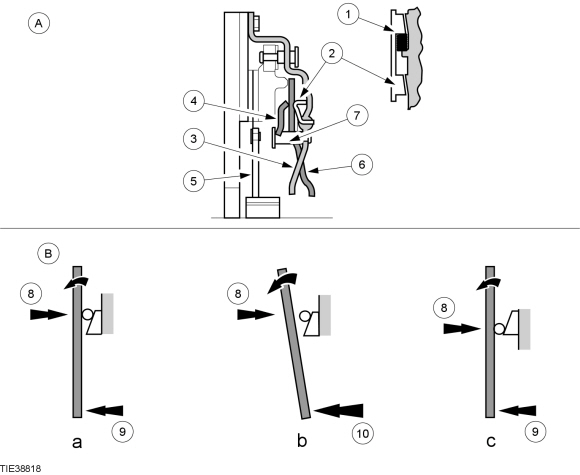
Self-adjusting Clutch Construction and Operation
| Item | Description |
|---|---|
| A | Cross-section of a self-adjusting clutch |
| B | Schematic representation of the diaphragm spring forces |
| a | Forces in equilibrium |
| b | Operating force of the clutch is higher than the sensing diaphragm spring |
| c | Forces in equilibrium after the outward turn |
| 1 | Compression spring |
| 2 | Ramp ring |
| 3 | Clutch housing |
| 4 | Sensing diaphragm spring |
| 5 | Clutch disc |
| 6 | Diaphragm spring |
| 7 | Studs |
| 8 | Force of the sensing diaphragm spring |
| 9 | Operating force |
| 10 | Increased operating force because of wear |
Part A of the illustration shows a cross-section through a self-adjusting clutch.
A key difference to conventional clutches is that the diaphragm spring is not riveted to the clutch housing, but supported through a sensing diaphragm spring.
The diaphragm spring is a floating fit on the studs. The ramp ring and pressure spring are shown vertically in illustration A for clarity. The ramp ring and pressure spring are actually installed in the engine running direction.
As long as the operating force is less than or equal to the force of the sensing diaphragm spring, the diaphragm spring remains in its original position (illustration B, diagram a). When outward turning of the diaphragm spring tongues becomes necessary because of wear, higher operating force must be applied.
The operating force and the sensing diaphragm spring force are no longer in equilibrium. The diaphragm spring pushes the sensing diaphragm spring back (illustration B, diagram b). There is a gap between the diaphragm spring and the ramp ring.
The pressure spring displaces the ramp ring, and the gap is closed again. The diaphragm spring and the sensing diaphragm spring take up a new position on the studs. The diaphragm spring tongues move from their outward angle back into their original position (illustration B, diagram c).
Ramp Ring Construction
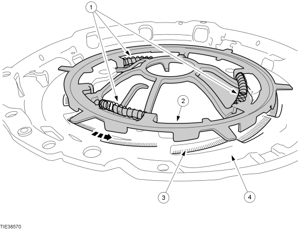
| Item | Description |
|---|---|
| 1 | Compression springs |
| 2 | Ramp ring |
| 3 | Ramp |
| 4 | Clutch housing |
The illustration shows the layout of the ramp ring.
The compression springs turn the ramp ring counterclockwise (CCW). The ramp ring is shown raised from its normal position for clarity.
Clutch Disc
Clutch Disc Components
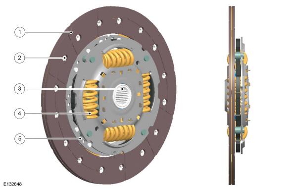
| Item | Description |
|---|---|
| 1 | Friction lining |
| 2 | Rivet |
| 3 | Multi-spline hub |
| 4 | Torsion spring |
| 5 | Carrier plate |
Clutch Disc Function
The clutch disc makes sure clutch engagement is vibration free, compensates for tolerances between the surfaces of the pressure plate and the flywheel, and reduces vibrations in the transmission.
Wear and generation of heat
Wear can be compensated for via an automatic adjustment mechanism.
Overheating of the clutch disc surface causes it to glaze. The friction lining surface may display cracks and start to become brittle. It is not a rare occurrence for individual segments of the friction lining surface to become detached. The coefficient of friction, and therefore the amount of torque which can be transmitted for a given clamp load, is reduced as a result of glazing.
This damage is not undone by normal wear.
If the friction lining is connected to the carrier plate with adhesive, the latter can become soft if the components overheat, and as a result the friction lining can be displaced or detached over large areas. If this happens the clutch will no longer function as intended.
On wet clutches, the coolant can be chemically changed as a result of continuously high temperatures. If oil is used as the coolant, this can lead to increased oxidation or to the cracking of oil molecules. Cracking means that the structure of the oil molecule chain is changed in comparison to the original structure. Changes to the oil molecule chain can have a detrimental effect on the function of the clutch.
A hot spot can occur if there is a local build-up of heat between the friction lining and the pressure plate as a result of a localized concentration of heat, this is referred to as a hot spot. The thermal peaks created in the process occur as a result of uneven accumulation of material on the friction lining and pressure plate.
Clutch Disc Function
On the inside, the multi-splines on the clutch disc hub allow it to be moved axially in relation to the transmission input shaft while not permitting any relative rotation.
The splines allow the clutch disc to release from the flywheel after the pressure plate has been lifted off. If this axial freedom of movement is no longer given, for example, due to rust, or the clutch disc has too much runout, the clutch will no longer fully disengage. Torque is then still transmitted from the engine to the transmission. This places correspondingly higher loads on the synchronizer assembly. This can result in difficult and noisy gearshifts.
During engagement of the clutch, the clutch disc is clamped between the pressure plate and the flywheel. If no dual-mass flywheel is fitted, coil springs which are arranged tangentially in the intermediate layers and which permit limited radial twisting provide damping for noises from the transmission (rattling) and other vibrations.
Cover assembly
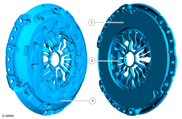
| Item | Description |
|---|---|
| 1 | Pressure plate |
| 2 | Diaphragm spring |
| 3 | Clutch cover |
Role of the cover assembly
The cover assembly comprises the pressure plate, diaphragm spring and clutch cover; it makes sure that sufficient contact pressure is applied. In addition, the cover assembly transmits the torque from the flywheel to the pressure plate and then onto the clutch disc.
Function of the cover assembly
If the clutch pedal is pressed as far as it will go, the actuating force for a diaphragm spring does not increase any further when the pressure point is exceeded. This avoids excessive axial loads being applied to the transmission synchronization.
Diaphragm spring
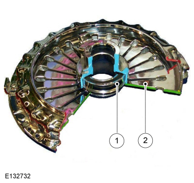
| Item | Description |
|---|---|
| 1 | Clutch release bearing |
| 2 | Diaphragm spring tongues |
Role of the diaphragm spring
The diaphragm spring acts as a transfer element between the clutch cover and the pressure plate.
Function of the diaphragm spring
A spring steel disc which has multiple slots and is slightly tapered towards the middle connects the clutch cover to the pressure plate. As a result of the preload of the spring steel disc, the pressure plate is pressed against the clutch disc when the clutch is engaged. To disengage, the release bearing presses against the pressure plate diaphragm spring tongues and pulls the pressure plate back and releases the clutch disc from the flywheel.
This design produces the greatest contact forces at the pressure point. If the clutch pedal is pressed beyond this point, the pressing forces are reduced by a diaphragm spring rather than coil springs.
Copyright © Ford Motor Company