| 308-02 Clutch Controls - Vehicles With: 5-Speed Manual Transmission - B5/IB5/6-Speed Manual Transmission - B6 | 2014 Fiesta |
| Description and Operation | Procedure revision date: 04/25/2013 |
System Operation
Hydraulic Clutch Actuation System
The design of the clutch actuation system is very similar to that of a hydraulic brake system.
The hydraulic clutch actuation system uses a hydraulic line rather than a mechanical connection to transmit the pedal movement. The forces are transmitted purely hydraulically and the brake fluid is used for drive transmission.
A clutch master cylinder actuates a clutch slave cylinder through a hydraulic line. When the operating force is released, the hydraulic clutch actuation system is depressurized and the clutch slave cylinder is pushed back by the diaphragm spring of the clutch mechanism. With this type of actuation, the clutch release bearing remains in constant contact with the surrounding diaphragm spring of the clutch mechanism. The clutch release bearing must therefore be at a permanently speed-resistant.
The hydraulic clutch actuation system is supplied by the brake fluid reservoir.
Displaced hydraulic fluid can escape from the clutch master cylinder's compensating bore into the reservoir provided for this purpose. This means that the hydraulic clutch actuation system is self-adjusting.
The CPP sensor is located on the clutch master cylinder and is not adjustable. An actuated clutch pedal activates the CPP sensor.
The hydraulic clutch actuation system consists of the following components:
Component Description
Clutch Master Cylinder
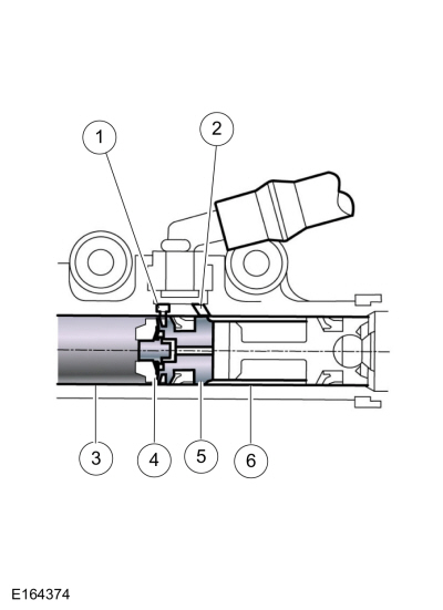
| Item | Description |
|---|---|
| 1 | Breather hole |
| 2 | Replenishing hole |
| 3 | Depressurized space |
| 4 | Pistons |
| 5 | Replenishing valve |
| 6 | Pressure chamber |
Function
The master cylinder is responsible for generating the fluid pressure for the hydraulic system.
When the piston is in the rest position, the volume in the pressure chamber and the reservoir is equalized via the compensating bore. When the piston moves over the compensating bore, fluid pressure builds up in the pressure chamber.
Operation
The hydraulic fluid is extracted from the brake fluid reservoir. This line ends in the clutch master cylinder. Due to the different piston diameters, a gear ratio can be set that reduces the pedal forces, e.g. when the diameter of the clutch master cylinder is smaller.
Clutch release bearings must withstand large axial forces. Previously, during normal driving, low play brought the vehicle to a stop when the clutch pedal was not actuated. The release bearing only rotated during engagement of a gear. Due to better protection against wear, current clutch release bearings always rotate. With hydraulic clutch actuation, the clutch slave cylinder can be integrated centrally in the clutch release bearing.
NOTICE: Long actuation of the clutch, e.g. at a red traffic light, creates an unnecessary load on the clutch release bearing, the clutch disc and the axial bearing of the crankshaft.
Clutch Slave Cylinder
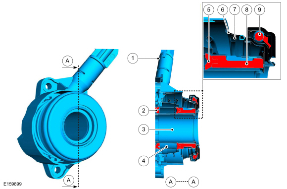
| Item | Description |
|---|---|
| A | Sectional plane A |
| 1 | Connection – pressure line with hydraulic duct to the pressure chamber |
| 2 | Oil seal |
| 3 | Sleeve |
| 4 | Pressure chamber |
| 5 | Packing |
| 6 | Gaiter |
| 7 | Pressure spring |
| 8 | Pistons |
| 9 | Clutch release bearing |
Function
The task of the clutch slave cylinder is to transmit the fluid pressure generated in the clutch master cylinder as a force for actuating the clutch release bearing.
Operation
In the clutch slave cylinder, the pressure moves the piston in the axial direction. In the process, the clutch release bearing presses against the diaphragm spring of the pressure plate and interrupts the frictional connection between the clutch disc and the flywheel.
The diaphragm spring causes the clutch release bearing to be preloaded when not actuated.
Copyright © Ford Motor Company