
| 303-01B Engine - 1.6L EcoBoost (132kW/180PS) - Sigma | 2014 Fiesta |
| Removal and Installation | Procedure revision date: 06/20/2013 |
Removal
NOTICE: During engine repair procedures, cleanliness is extremely important. Any foreign material (including any material created while cleaning gasket surfaces) that enters the oil passages, coolant passages or the oil pan can cause engine failure.
NOTICE: Do not rotate the camshafts unless instructed to in this procedure. Rotating the camshafts or crankshaft with timing components loosened or removed can cause serious damage to the valves and pistons.
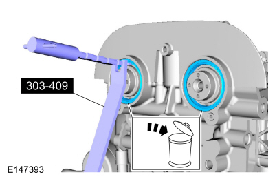
NOTICE: Use a heat gun to soften the flange sealant, this will aid in the removal of the camshaft mega cap. Failure to follow these directions may result in damage to the camshaft mega cap.
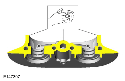
NOTE: Note the location and orientation of each camshaft bearing cap and the position of the camshaft lobes on the No. 1 cylinder for installation reference.
General Equipment : Hot Air Gun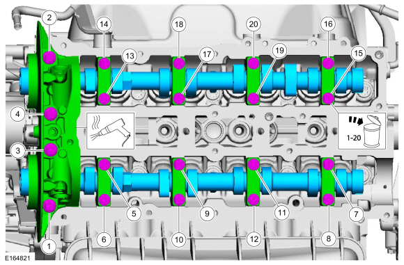
Installation
NOTICE: If any new parts are being installed (cylinder head, valves, tappets, camshafts) it is necessary to check the valve clearance, follow the next 12 steps exactly or serious damage to the engine may occur. If the original parts are being installed it is not necessary to check the valve clearance so proceed to step 13.
Place a paint mark on the crankshaft at the 12 o'clock position.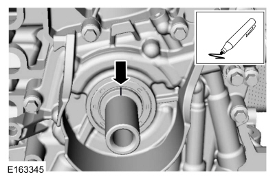
NOTE: Rotating the crankshaft will position all of the pistons below the deck of the cylinder block and allow the camshafts to be installed and the valve clearance checked without the possibility of damage to the valves or pistons.
Using the crankshaft bolt and washer, rotate the crankshaft clockwise 270 degrees until the paint mark is at the 9 o'clock position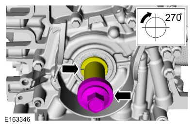
NOTICE: Failure to follow the camshaft tightening procedure can result in damage to the camshafts.
NOTE: Make sure that the components are installed to the location and orientation noted before removal.
NOTE: Make sure that the mating faces are clean and free of foreign material.
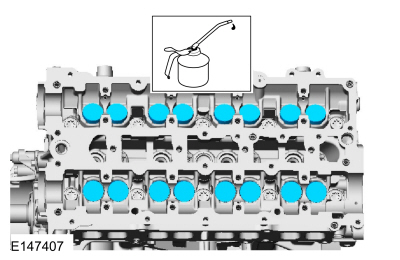
NOTE: Apply clean engine oil to the bearing surfaces of the camshafts, camshaft bearing caps and the VCT bridge.
Tighten the bolts evenly, half a turn at a time, until the camshaft bearing caps and the VCT bridge are seated against the cylinder head.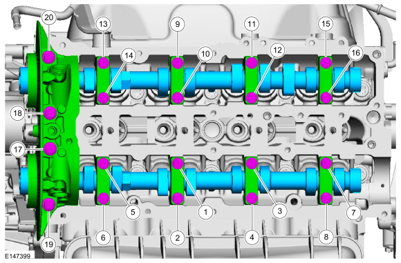
NOTE: Select tappets using this formula: ideal tappet thickness = measured clearance + the existing tappet thickness - nominal clearance. Select the closest tappet size to the ideal tappet thickness available and mark the installation location.
NOTE: The nominal clearance is 0.0079 in ( .2 mm) for intake and 0.0134 in ( .34 mm) for exhaust.
NOTE: The acceptable clearances after being fully installed is 0.007 –0.009 in ( .17 –.23 mm) for intake and 0.012 –0.015 in ( .31 –.37 mm) for exhaust.
NOTICE: Failure to follow the camshaft loosening procedure can result in damage to the camshafts.
NOTE: Note the location and orientation of each camshaft bearing cap and the position of the camshaft lobes on the No. 1 cylinder for installation reference.
Loosen the camshaft bearing caps in sequence 2 turns at a time until all tension is released from the camshaft bearing caps in sequence shown.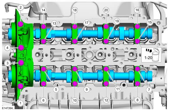
NOTE: Rotating the crankshaft will position the engine at TDC and allow you to install the camshafts in the same position as noted during the disassembly.
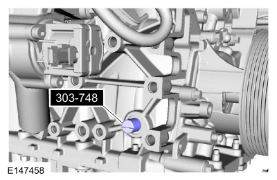
Rotate the crankshaft clockwise 90 degrees so the crankshaft contacts the Timing Peg, Crankshaft TDC 303-748.
NOTE: Verify the crankshaft contacts the Timing Peg and the engine is still at TDC
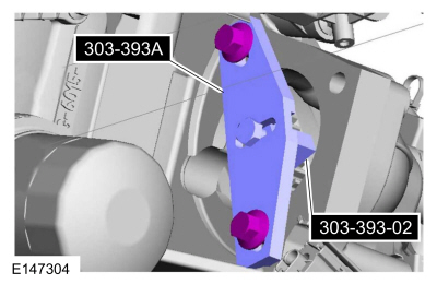
Install Special Service Tool : 303-393A Locking Tool, Flywheel , 303-393-02 Adapter for 303-393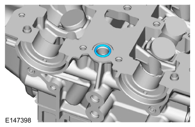
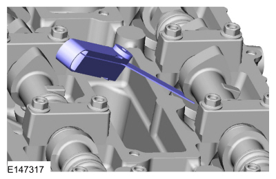
NOTE: The component must be installed within 5 minutes of applying the sealant.
Material : Flange Sealant / CU7Z-19B508-A (WSS-M2G348-A11)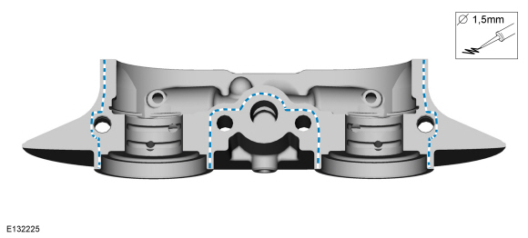
NOTICE: Failure to follow the camshaft tightening procedure can result in damage to the camshafts.
NOTE: Make sure that the components are installed to the location and orientation noted before removal.
NOTE: Make sure that the mating faces are clean and free of foreign material.
NOTE: Apply clean engine oil to the bearing surfaces of the camshafts, camshaft bearing caps and the VCT bridge.
NOTE: Make sure that new bolts are installed.
Tighten the bolts evenly, half a turn at a time, until the camshaft bearing caps and the VCT bridge are seated against the cylinder head.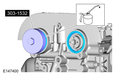
Copyright © Ford Motor Company