
| 303-01B Engine - 1.6L EcoBoost (132kW/180PS) - Sigma | 2014 Fiesta |
| Assembly | Procedure revision date: 07/2/2013 |
NOTICE: During engine repair procedures, cleanliness is extremely important. Any foreign material, including any material created while cleaning gasket surfaces that enters the oil passages, coolant passages or the oil pan, can cause engine failure.
NOTE: Refer to exploded views in Description and Operation.
NOTICE: The rod cap installation must keep the same orientation as marked during disassembly or engine damage may occur.
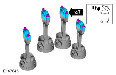
Use the original connecting rod cap bolts.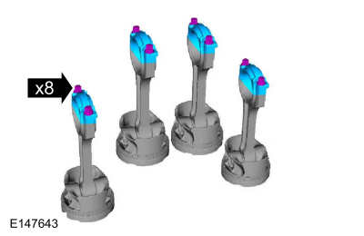
NOTE: Before assembling the cylinder block, all sealing surfaces must be free of chips, dirt, paint and foreign material. Also, make sure the coolant and oil passages are clear.
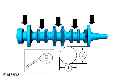
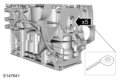
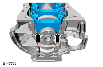
NOTE: If reusing the crankshaft main bearings, install them in their original positions and orientation as noted during disassembly.
Material : Motorcraft® SAE 5W-20 Premium Synthetic Blend Motor Oil / XO-5W20-QSP (WSS-M2C945-A)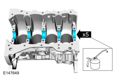
NOTE: If reusing the crankshaft main bearings, install them in their original positions and orientation as noted during disassembly.
Material : Motorcraft® SAE 5W-20 Premium Synthetic Blend Motor Oil / XO-5W20-QSP (WSS-M2C945-A)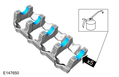
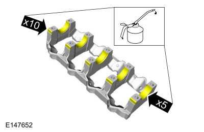
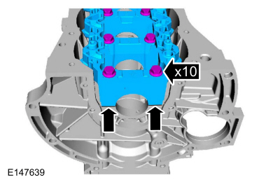
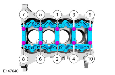
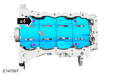
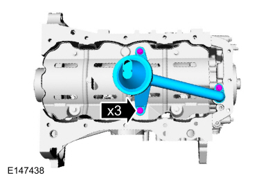
NOTE: Lubricate the main bearing beam bolts threads with clean engine oil.
Material : Motorcraft® SAE 5W-20 Premium Synthetic Blend Motor Oil / XO-5W20-QSP (WSS-M2C945-A)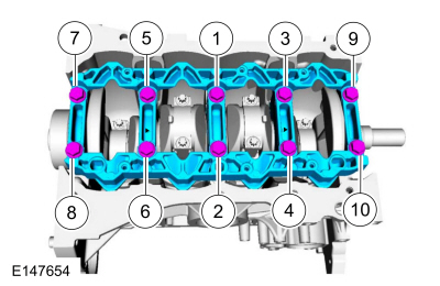
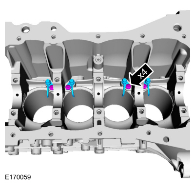
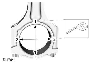
NOTE: If reusing the connecting rod bearings, install them in their original positions and orientation as noted during disassembly.
Material : Motorcraft® SAE 5W-20 Premium Synthetic Blend Motor Oil / XO-5W20-QSP (WSS-M2C945-A)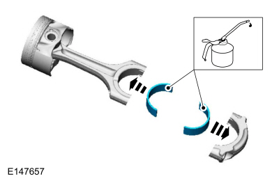
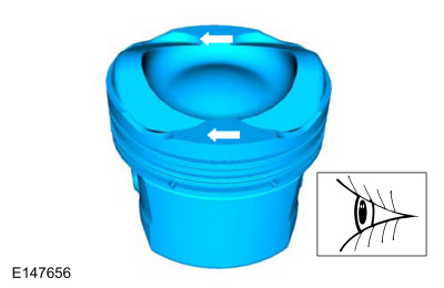
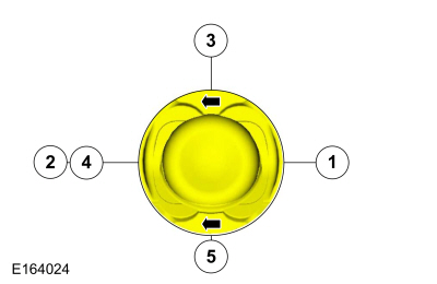
NOTE: The upper and lower compression rings are to be fitted with the identification marks on the upper side.
NOTE: Arrows faces the front of the engine.
NOTE: Align the piston rings on the piston.
NOTE: Using a connecting rod installer will unsure not to scratch the cylinder wall or crankshaft journal with the connecting rod. Push the piston down until the connecting rod bearing seats on the crankshaft journal.
NOTE: Make sure the piston arrows on top is facing toward the front of the engine.
General Equipment : Piston Ring Compressor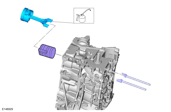
NOTICE: The rod cap installation must keep the same orientation as marked during disassembly or engine damage may occur.
NOTE: Install connecting rod caps and bolts on the connecting rods for cylinders 1 and 4 first and tighten. Then rotate crankshaft 180 degrees and install connecting rod caps and bolts on connecting rods for cylinders 2 and 3 and tighten.
NOTE: After installation of each connecting rod cap, rotate the crankshaft to verify smooth operation.
Use new connecting rod caps bolts.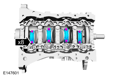
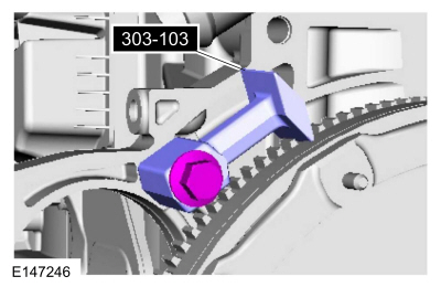
NOTE: Only rotate the crankshaft clockwise direction.
Rotate the crankshaft slowly clockwise until the crankshaft balance weight is up against the crankshaft locking tool. The engine is now at TDC .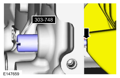
NOTE: There are different length of bolts noted in disassembly.
Finger tight at this stage.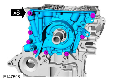
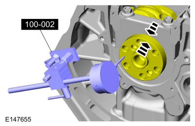
NOTE: New crankshaft rear seal is supplied with an alignment sleeve which must be removed after installation.
NOTE: Do not remove the alignment sleeve from the crankshaft rear seal prior to installation on the crankshaft.
Align the crankshaft rear seal and alignment sleeve on the crankshaft and push the crankshaft rear seal off the alignment sleeve onto the crankshaft without stopping until the crankshaft rear seal meets the cylinder block.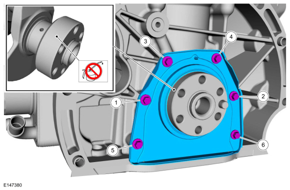
NOTE: Only rotate the crankshaft clockwise direction.
Verify the crankshaft balance weight is up against the crankshaft locking tool.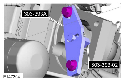
NOTE: The O-ring seal is to be reused unless damaged.
NOTICE: Do not use metal scrapers, wire brushes, power abrasive discs or other abrasive means to clean the sealing surfaces. These tools cause scratches and gouges, which make leak paths. Use a plastic scraping tool to remove traces of sealant.
Make sure that the mating faces are clean and free of foreign material.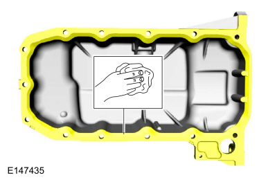
NOTICE: Do not use metal scrapers, plastic scrapers, wire brushes, power abrasive discs or other abrasive means to clean the sealing surfaces. These tools cause scratches and gouges, which make leak paths.
NOTE: Make sure that the mating faces are clean and free of foreign material.
Do not use any type of scrapers. There is a rubber sealing surface on the bottom of the crankshaft rear seal, take extra care when cleaning the specified area by peeling off the old sealant by hand.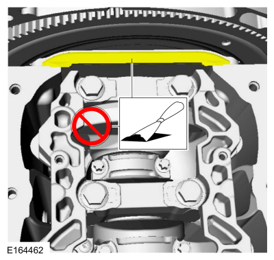
NOTICE: Do not use metal scrapers, wire brushes, power abrasive discs or other abrasive means to clean the sealing surfaces. These tools cause scratches and gouges, which make leak paths. Use a plastic scraping tool to remove traces of sealant.
NOTE: Make sure that the mating faces are clean and free of foreign material.
Clean only the specified area with the specified material and a plastic scraping tool to remove traces of sealant.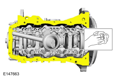
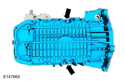
NOTE: The use of the two studs will aid on the alignment of the oil pan.
Two M8x20 studs.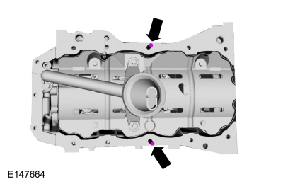
NOTE: The component must be installed within 5 minutes of applying the sealant.
Material : Silicone Gasket and Sealant / TA-30 (WSE-M4G323-A4)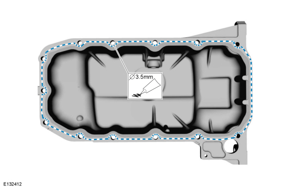
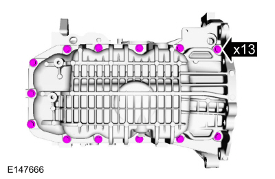
NOTE: Only tighten the bolts finger tight at this stage.
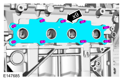
NOTICE: Do not use metal scrapers, wire brushes, power abrasive discs or other abrasive means to clean the sealing surfaces. These tools cause scratches and gouges that make leak paths. Use a plastic scraping tool to remove all traces of the head gasket.
NOTE: If there is no residual gasket material present, metal surface prep can be used to clean and prepare the surfaces.
Material : Motorcraft® Metal Surface Prep / ZC-31-A
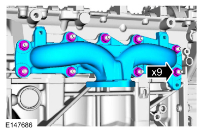
NOTE: The cylinder head bolts are torque-to-yield and must not be reused. New cylinder head bolts must be installed.
NOTE: Make sure that no fluids are present in the cylinder head bolt threaded bores.
Torque :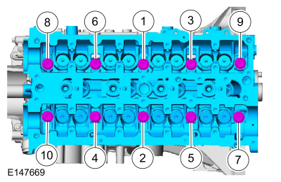
NOTICE: If any new parts are being installed (cylinder head, valves, tappets, camshafts) it is necessary to check the valve clearance, follow the next 10 steps exactly or serious damage to the engine may occur. If the original parts are being installed it is not necessary to check the valve clearance so proceed to step 68.
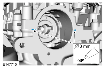
Place a paint mark on the crankshaft at the 12 o'clock position.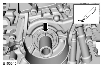
NOTE: Rotating the crankshaft will position all of the pistons below the deck of the cylinder block and allow the camshafts to be installed and the valve clearance checked without the possibility of damage to the valves or pistons.
Using the crankshaft bolt and washer, rotate the crankshaft clockwise 270 degrees until the paint mark is at the 9 o'clock position.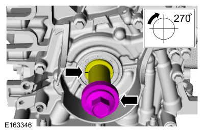
NOTICE: Failure to follow the camshaft tightening procedure can result in damage to the camshafts.
NOTE: Make sure that the components are installed to the location and orientation noted before removal.
NOTE: Make sure that the mating faces are clean and free of foreign material.
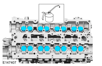
NOTE: Apply clean engine oil to the bearing surfaces of the camshafts, camshaft bearing caps and the VCT bridge.
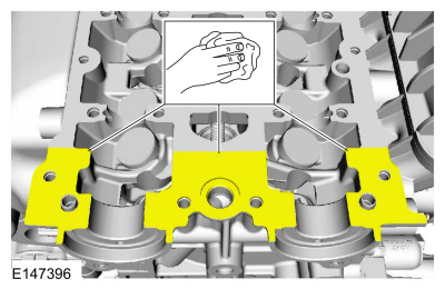
Tighten the bolts evenly, half a turn at a time, until the camshaft bearing caps and the VCT bridge are seated against the cylinder head.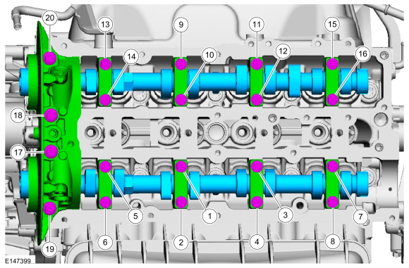
NOTE: Select tappets using this formula: ideal tappet thickness = measured clearance + the existing tappet thickness - nominal clearance. Select the closest tappet size to the ideal tappet thickness available and mark the installation location.
NOTE: The nominal clearance is 0.0079 in ( .2 mm) for intake and 0.0134 in ( .34 mm) for exhaust.
NOTE: The acceptable clearances after being fully installed is 0.007 –0.009 in ( .17 –.23 mm) for intake and 0.012 –0.015 in ( .31 –.37 mm) for exhaust.
NOTICE: Failure to follow the camshaft loosening procedure can result in damage to the camshafts.
NOTE: Note the location and orientation of each camshaft bearing cap and the position of the camshaft lobes on the No. 1 cylinder for installation reference.
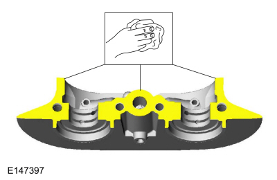
Loosen the camshaft bearing caps in sequence 2 turns at a time until all tension is released from the camshaft bearing caps in sequence shown.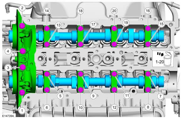
NOTE: Rotating the crankshaft will position the engine at TDC and allow you to install the camshafts in the same position as noted during the disassembly.
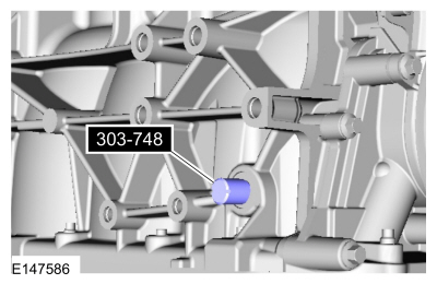
Rotate the crankshaft clockwise 90 degrees so the crankshaft contacts the Timing Peg, Crankshaft TDC 303-748.
NOTE: Verify the crankshaft contacts the Timing Peg and the engine is still at TDC
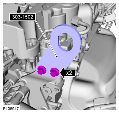
Install Special Service Tool : 303-393A Locking Tool, Flywheel , 303-393-02 Adapter for 303-393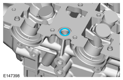
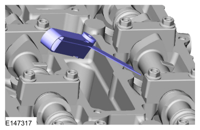
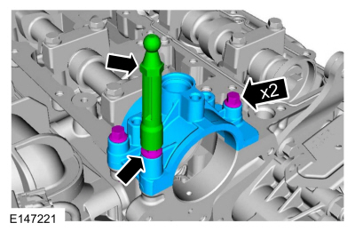
NOTE: Make sure that the mating faces are clean and free of foreign material.
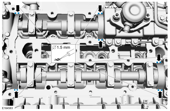
NOTE: The VCT bridge must be installed within 5 minutes of applying the gasket maker.
Material : Flange Sealant / CU7Z-19B508-A (WSS-M2G348-A11)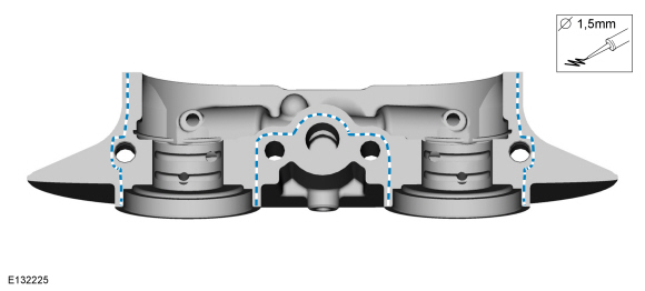
NOTICE: Failure to follow the camshaft tightening procedure can result in damage to the camshafts.
NOTE: Make sure that the components are installed to the location and orientation noted before removal.
NOTE: Make sure that the mating faces are clean and free of foreign material.
NOTE: Make sure that new bolts are installed.
NOTE: Apply clean engine oil to the bearing surfaces of the camshafts, camshaft bearing caps and the VCT bridge.
Tighten the bolts evenly, half a turn at a time, until the camshaft bearing caps and the VCT bridge are seated against the cylinder head.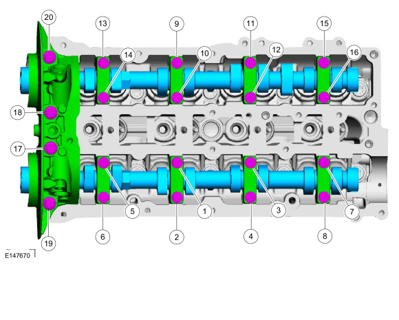
NOTE: It may be necessary to use an open-ended wrench to turn the camshafts by the hexagon to align the camshafts.
Install Special Service Tool : 303-1552 Alignment Tool, Camshaft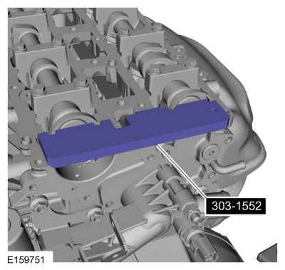
NOTE: Use an open-ended wrench to hold the camshafts by the hexagon to prevent the camshafts from turning.
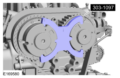
Install Special Service Tool : 303-1097 Locking Tool, Variable Camshaft Timing Oil Control Unit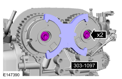
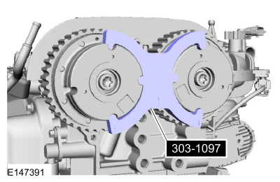
NOTE: Use an open-ended wrench to hold the camshafts by the hexagon to prevent the camshafts from turning.
Torque : Tighten an additional 75°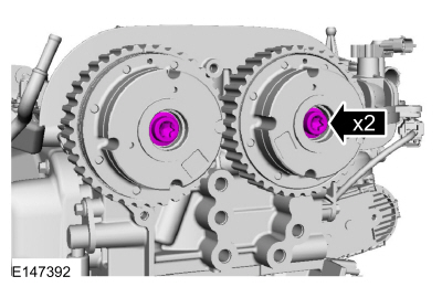
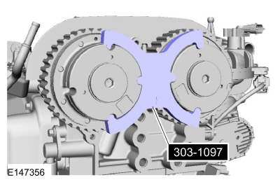
NOTE: The special tool can only be installed if the valve timing is correct.
If the special tools cannot be installed, repeat the adjustment according to the preceding steps.NOTE: Use an open-ended wrench to hold the camshafts by the hexagon to prevent the camshafts from turning.
Torque : 16 Nm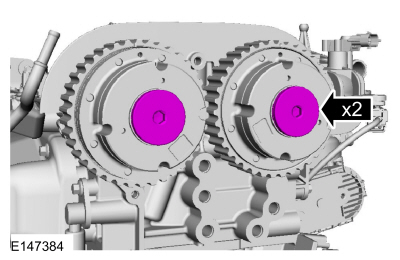
NOTE: Make sure that the mating faces are clean and free of foreign material.
 WARNING:
The timing belt tensioner spring is under load. Extra care must be taken at all times when handling the tensioner. Failure
to follow this instruction may result in personal injury.
WARNING:
The timing belt tensioner spring is under load. Extra care must be taken at all times when handling the tensioner. Failure
to follow this instruction may result in personal injury.
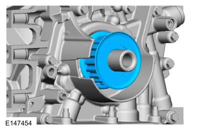
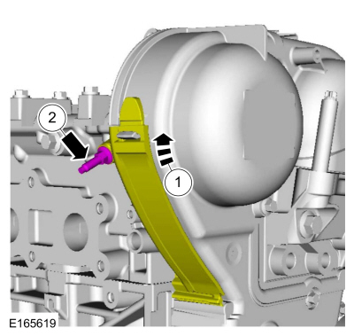
NOTE: Before installation, clean and inspect the sprocket for any damage. If damage is evident, replace the sprocket. If no damage, the sprocket is to be reused.
WARNING:
The timing belt tensioner spring is under load. Extra care must be taken at all times when handling the tensioner. Failure
to follow this instruction may result in personal injury.
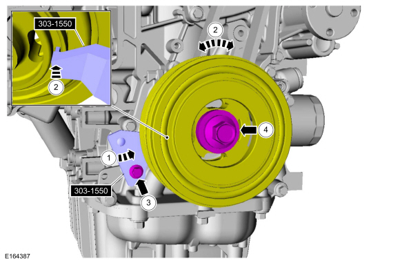
NOTE: Only rotate the crankshaft in a clockwise direction.
Rotate about 1 3/4 turns.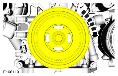
NOTE: Only rotate the crankshaft in a clockwise direction.
Rotate the crankshaft slowly clockwise until the crankshaft balance weight is up against the crankshaft locking tool. The engine is now at TDC .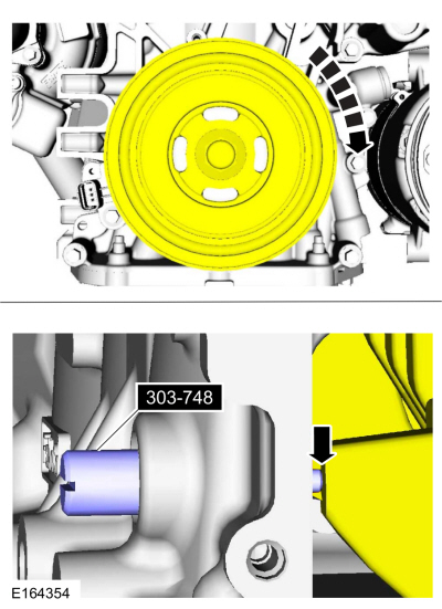
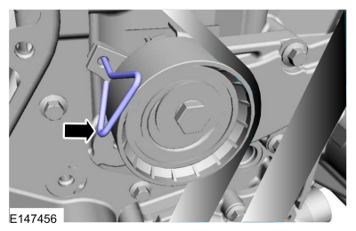
NOTE: It may necessary to rotate the camshafts slightly to install the special tool.
NOTE: The special tool can only be installed if the valve timing is correct.
If the special tool cannot be installed, repeat the adjustment according to the preceding steps.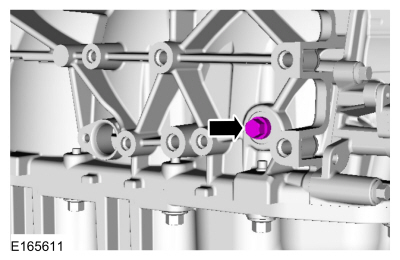
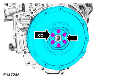
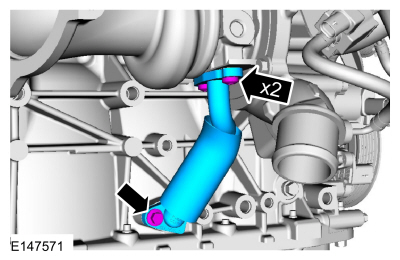
NOTE: There are different length of bolts noted in disassembly.
Torque : 55 Nm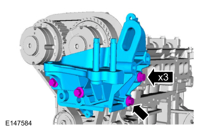
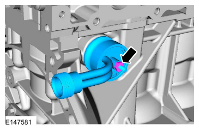
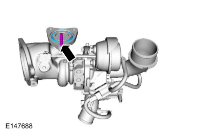
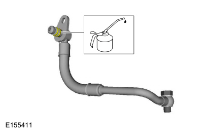
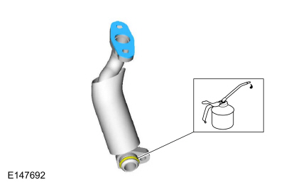
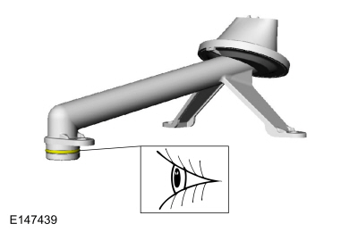
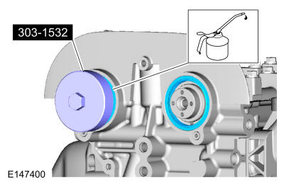
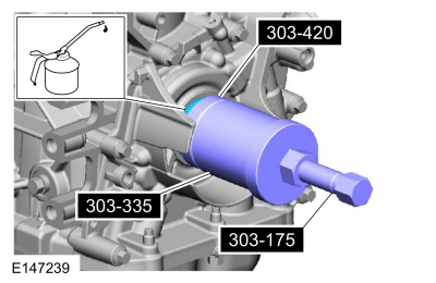
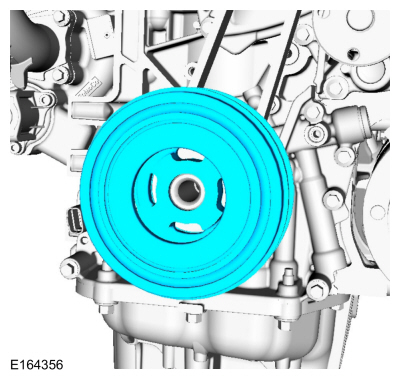
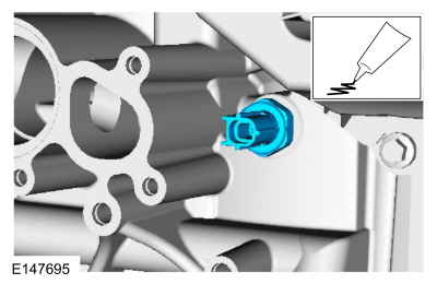
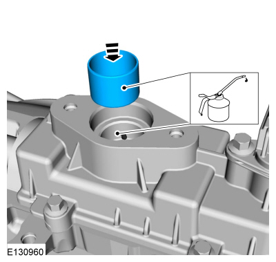
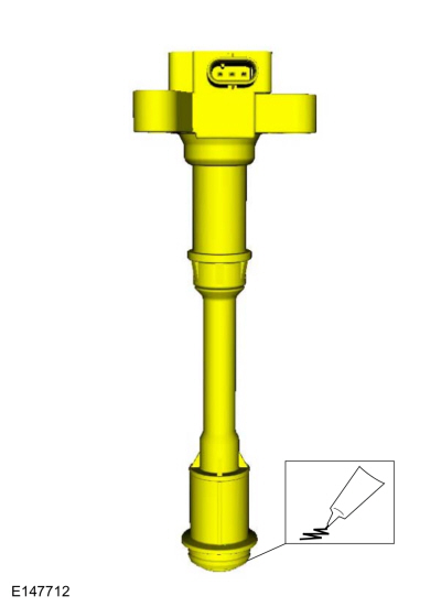
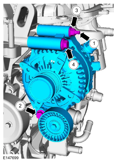
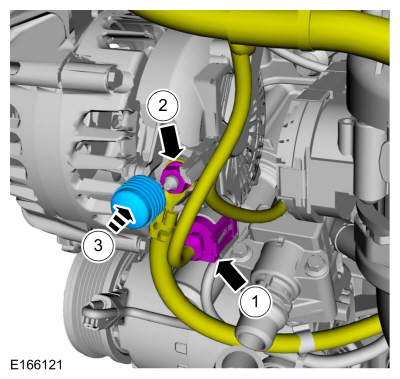
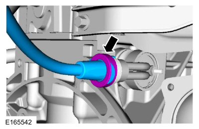
NOTE: Lubricate the spigot with clean engine oil.
.
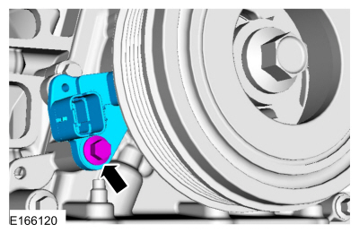
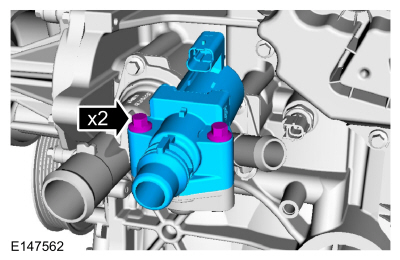
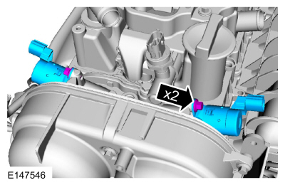
NOTE: The head of the KS should not touch any other component.
NOTE: The LH KS must be at the 10 o'clock position and the RH KS must be at the 2 o'clock position.
Torque : 18 Nm
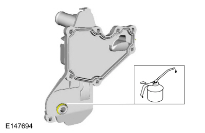
NOTICE: A new oil cooler must be installed or severe damage to the engine can occur.
Torque : 55 Nm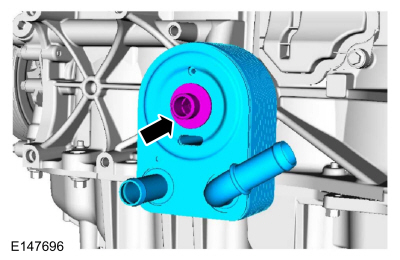
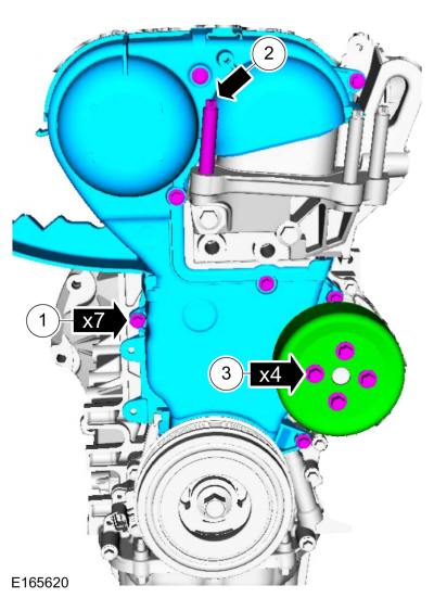
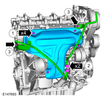
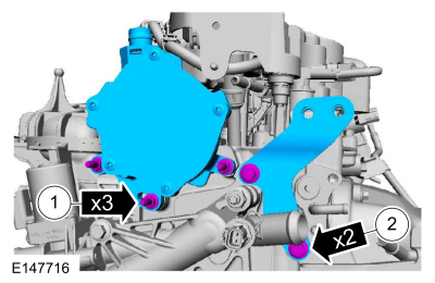
NOTE: There are different length of bolts noted in disassembly.
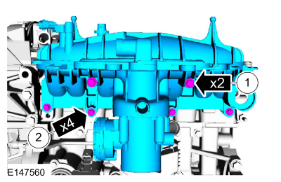
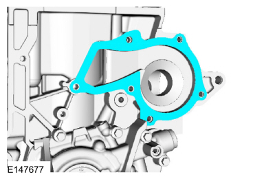
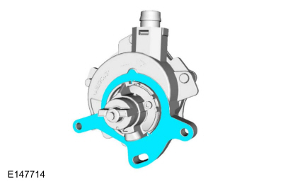
NOTICE: Do not use metal scrapers, wire brushes, power abrasive discs or other abrasive means to clean the sealing surfaces. These tools cause scratches and gouges which make leak paths.
Make sure that the mating faces are clean and free of foreign material.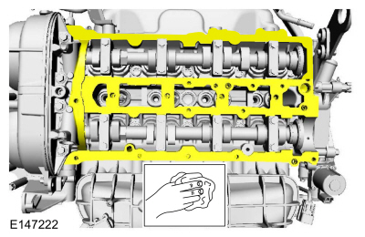
NOTICE: Do not use metal scrapers, wire brushes, power abrasive discs or other abrasive means to clean the sealing surfaces. These tools cause scratches and gouges which make leak paths.
Make sure that the mating faces are clean and free of foreign material.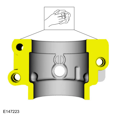
NOTICE: Do not use metal scrapers, wire brushes, power abrasive discs or other abrasive means to clean the sealing surfaces. These tools cause scratches and gouges which make leak paths.
Make sure that the mating faces are clean and free of foreign material.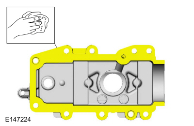
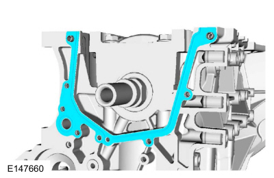
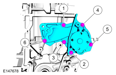
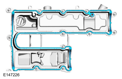
NOTE: The components must be installed within 5 minutes of applying the sealant.
Material : Flange Sealant / CU7Z-19B508-A (WSS-M2G348-A11)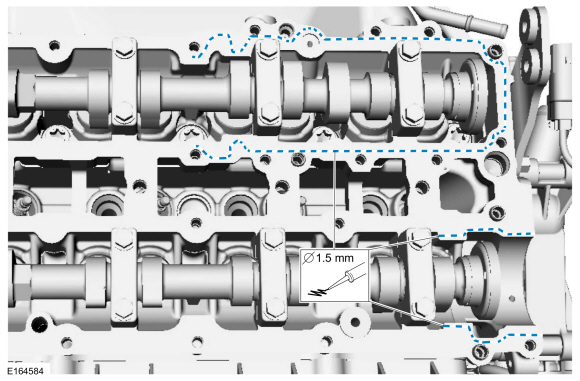
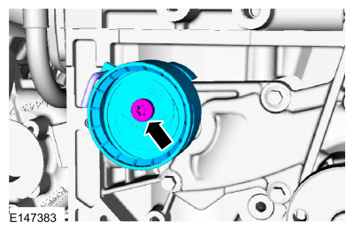
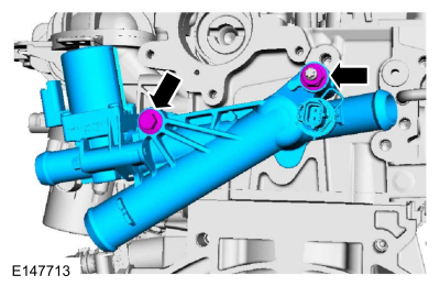
NOTE: Use a new O-ring seal.
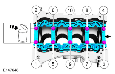
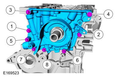
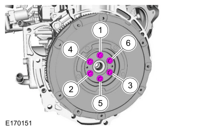
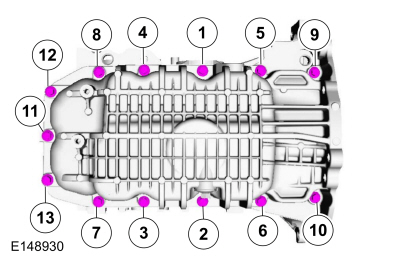
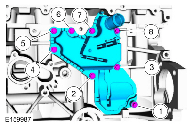
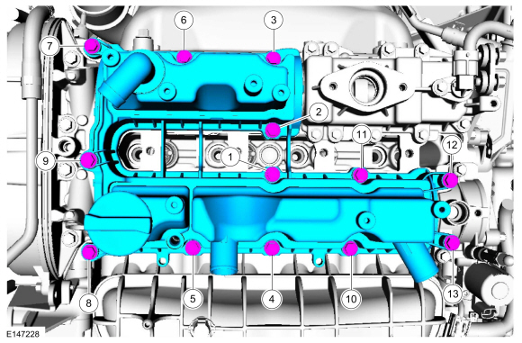
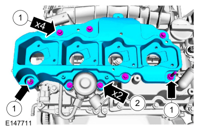
Tighten bolts 1 through 10 to: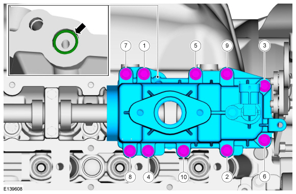
NOTE: The components must be installed within 5 minutes of applying the sealant.
Material : Flange Sealant / CU7Z-19B508-A (WSS-M2G348-A11)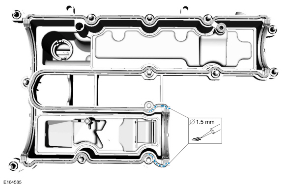
NOTE: A clean working environment is essential to prevent dirt or foreign material contamination.
NOTE: Make sure to thoroughly clean any residual fuel or foreign material from the cylinder head, block and the general surrounding area of the fuel rails and injectors.
NOTE: Do not use compressed air to clean the tip of the fuel injector.
NOTE: Do not use a brush to clean the tip of the fuel injector.
Special Tool(s) : 310-205 Fuel Injector Brush
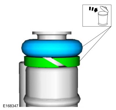
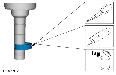
NOTICE: Use care when removing the lower Teflon® seals, not to scratch, nick or gouge the fuel injectors.
NOTICE: Do not attempt to cut the lower Teflon® seal without first pulling it away from the fuel injector or damage to the injector may occur.
NOTE:
NOTICE: Do not lubricate the new lower Teflon® fuel injector seals.
NOTICE: Once the Teflon® seal is installed on the Teflon® Seal Guide, it should immediately be installed onto the fuel injector to avoid excessive expansion of the Teflon® seal.
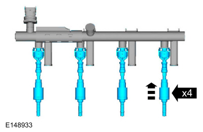
NOTE: Make sure that new lower fuel injector Teflon® seals are installed.
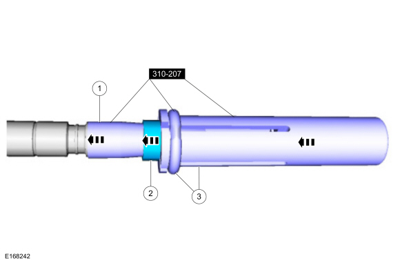
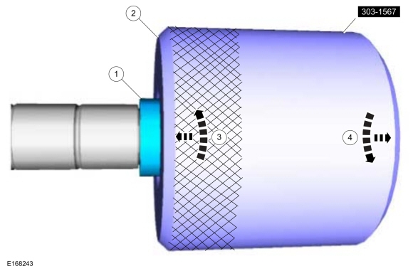
NOTICE: Install the fuel injectors into the cylinder head within 15 minutes of sizing the seals due to Teflon® seal expansion.
NOTE: Make sure the Teflon® seal is fully seated in the groove on the fuel injector before sizing the Teflon® seal.
NOTICE: Use fuel injector O-ring seals that are made of special fuel-resistant material. The use of ordinary O-ring seals may cause the fuel system to leak. Do not reuse the O-ring seals.
NOTE: Do not lubricate the new lower Teflon® fuel injector seals.
Material : Motorcraft® SAE 5W-20 Premium Synthetic Blend Motor Oil / XO-5W20-QSP (WSS-M2C945-A)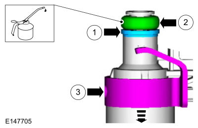
NOTE: The anti-rotation finger of the fuel injector clip must slip into the groove of the fuel rail cup.
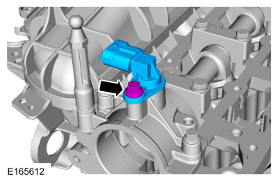
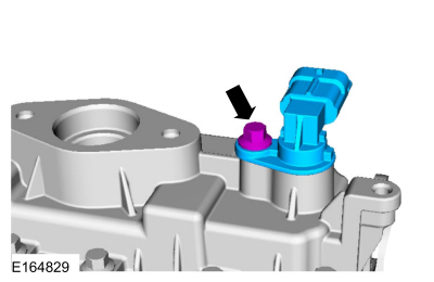
NOTE: The fuel rail pressure sensor must be replaced if it is removed from the fuel rail.
NOTE: Take extra care when handling the components.
Only use moderate force.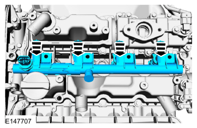
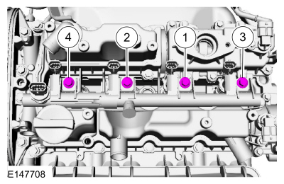
NOTE: Install all the bolts finger tight before final tightening.
NOTE: Make sure that a new component is installed.
NOTE: Calculate the correct torque wrench setting for the following torque. Refer to Torque Wrench Adapter Formulas.
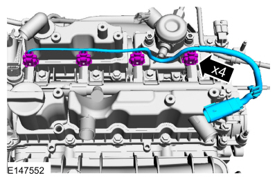
NOTE: Make sure that a new component is installed.
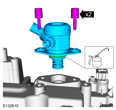
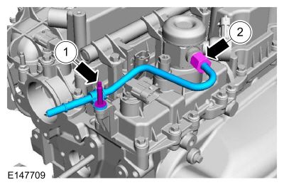
NOTE: Only tighten the 2 high pressure fuel tube flare nuts finger tight at this stage.
NOTE: Calculate the correct torque wrench setting for the following torque. Refer to Torque Wrench Adapter Formulas.
Torque :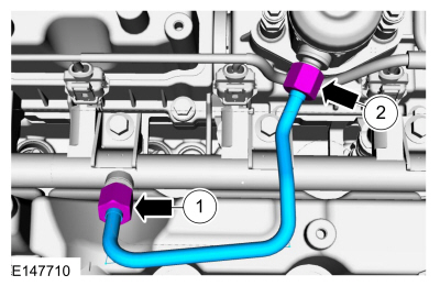
NOTE: When removing or installing the fuel injection pump noise insulator, spreading the openings will reduce the risk of damage.
Torque : 10 Nm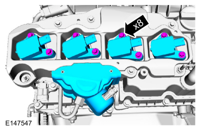
NOTE: The O-ring seals are to be reused unless damaged.
Material : Motorcraft® SAE 5W-20 Premium Synthetic Blend Motor Oil / XO-5W20-QSP (WSS-M2C945-A)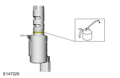
NOTE: Make sure that the mating faces are clean and free of foreign material.
NOTE: Install new O-ring seals and gasket seals.
Torque : 15 Nm
NOTICE: Do not breathe dust or use compressed air to blow dust from storage containers or friction components. Remove dust using government-approved techniques. Friction component dust may be a cancer and lung disease hazard. Exposure to potentially hazardous components may occur if dusts are created during repair of friction components, such as brake pads and clutch discs. Exposure may also cause irritation to skin, eyes and respiratory tract, and may cause allergic reactions and/or may lead to other chronic health effects. If irritation persists, seek medical attention or advice. Failure to follow these instructions may result in serious personal injury.
Using a clutch aligner, centralize the clutch disc to the clutch pressure plate.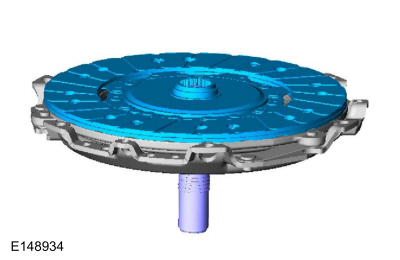
NOTICE: Do not breathe dust or use compressed air to blow dust from storage containers or friction components. Remove dust using government-approved techniques. Friction component dust may be a cancer and lung disease hazard. Exposure to potentially hazardous components may occur if dusts are created during repair of friction components, such as brake pads and clutch discs. Exposure may also cause irritation to skin, eyes and respiratory tract, and may cause allergic reactions and/or may lead to other chronic health effects. If irritation persists, seek medical attention or advice. Failure to follow these instructions may result in serious personal injury.
Torque : 29 Nm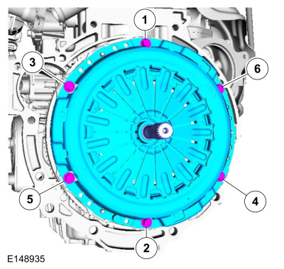
Copyright © Ford Motor Company