
| 303-01B Engine - 1.6L EcoBoost (132kW/180PS) - Sigma | 2014 Fiesta |
| Removal and Installation | Procedure revision date: 05/15/2013 |
Removal
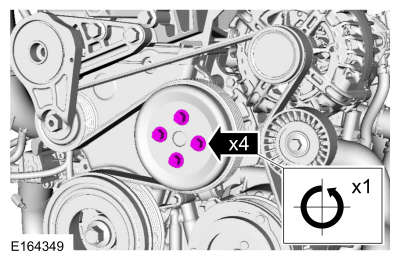
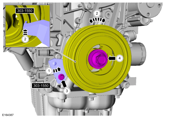
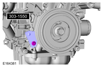
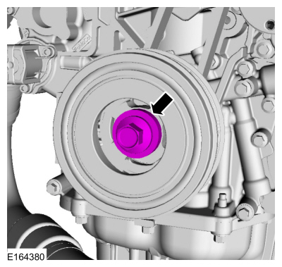
NOTE: Do not loosen or remove the crankshaft pulley bolt without first installing the special tools. The crankshaft pulley and the crankshaft timing sprocket are not keyed to the crankshaft. Before any repair requiring loosening or removal of the crankshaft pulley bolt, the crankshaft and camshafts must be locked in place by the special service tools, otherwise severe engine damage can occur.
NOTE: During engine repair procedures, cleanliness is extremely important. Any foreign material, including any material created while cleaning gasket surfaces, that enters the oil passages, coolant passages or the oil pan can cause engine failure.
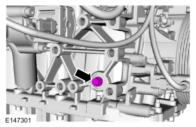
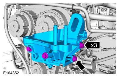
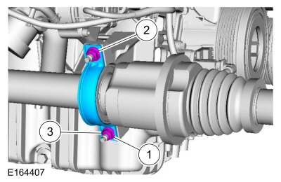
NOTE: It may be necessary to rotate the halfshaft to remove the front lower bolt.
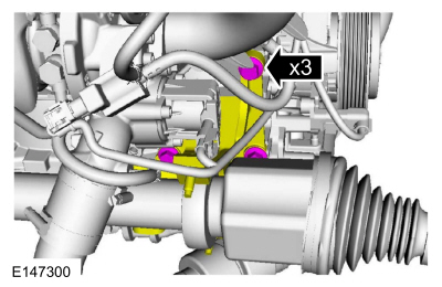
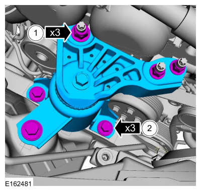

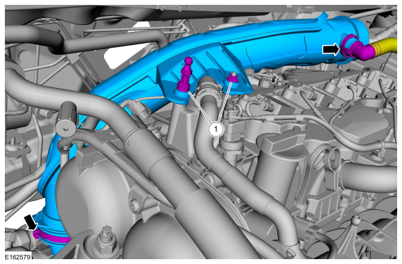
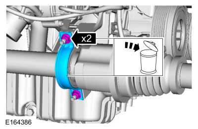
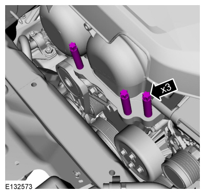
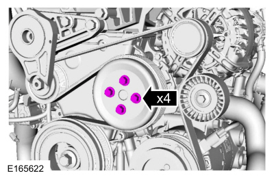
NOTE: Note the different lengths of the bolts for installation.
NOTE: Only rotate the crankshaft in a clockwise direction.
11 o'clock position.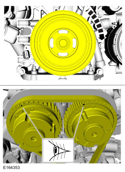
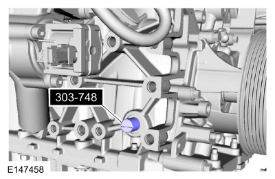
NOTE: The Crankshaft TDC Timing Pin will contact the crankshaft and prevent it from turning past TDC . However, the crankshaft can still be rotated in the counterclockwise direction. The crankshaft must remain at the TDC position during the crankshaft pulley removal and installation.
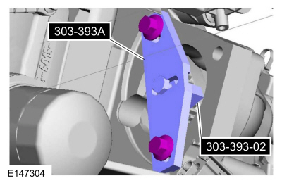
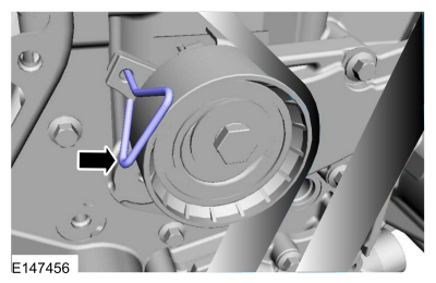
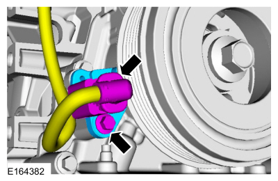
Install Special Service Tool : 303-748 Locking Tool, Crankshaft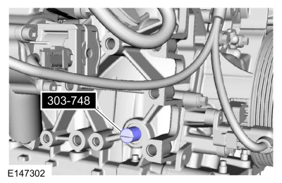
NOTE: Only rotate the crankshaft clockwise direction.
Rotate the crankshaft slowly clockwise until the crankshaft balance weight is up against the crankshaft locking tool. The engine is now at TDC .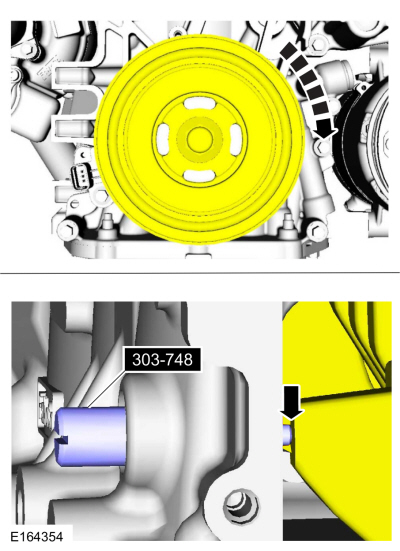
NOTE: It may necessary to rotate the camshafts slightly to install the special tool.
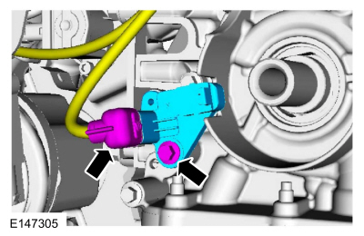
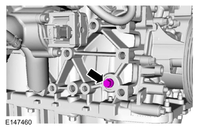
Install Special Service Tool : 303-1097 Locking Tool, Variable Camshaft Timing Oil Control Unit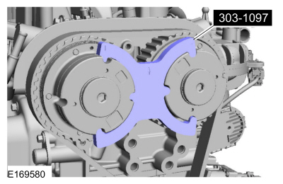
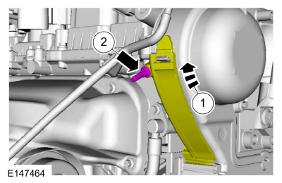
 WARNING:
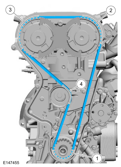
The timing belt tensioner spring is under load. Extra care must be taken at all times when handling the tensioner. Failure
to follow this instruction may result in personal injury.
WARNING:
The timing belt tensioner spring is under load. Extra care must be taken at all times when handling the tensioner. Failure
to follow this instruction may result in personal injury.
Installation
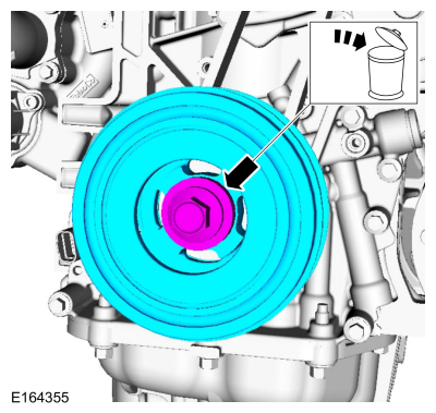
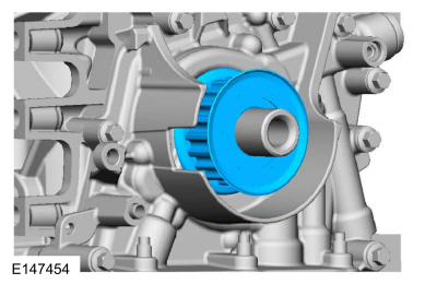
NOTE: Before installation, clean and inspect the sprocket for any damage. If damage is evident, replace the sprocket. If no damage, the sprocket is to be reused.
WARNING:
The timing belt tensioner spring is under load. Extra care must be taken at all times when handling the tensioner. Failure
to follow this instruction may result in personal injury.
NOTE: Only rotate the crankshaft in a clockwise direction.
Rotate about 1 3/4 turns.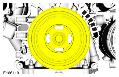
NOTE: Only rotate the crankshaft in a clockwise direction.
Rotate the crankshaft slowly clockwise until the crankshaft balance weight is up against the crankshaft locking tool. The engine is now at TDC .NOTE: It may necessary to rotate the camshafts slightly to install the special tool.
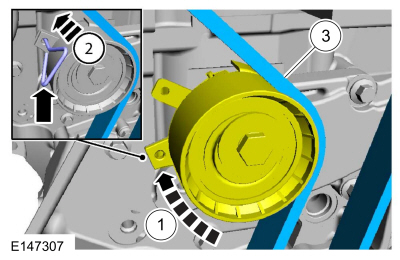
NOTE: The special tool can only be installed if the valve timing is correct.
If the special tool cannot be installed, repeat the adjustment according to the preceding steps.NOTE: There are different length of bolts noted in removal.
Torque : 55 Nm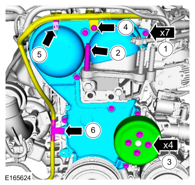
Copyright © Ford Motor Company