| 308-03A Manual Transmission - Vehicles With: 5-Speed Manual Transmission - B5/IB5 | 2014 Fiesta |
| Description and Operation | Procedure revision date: 05/14/2013 |
System Operation
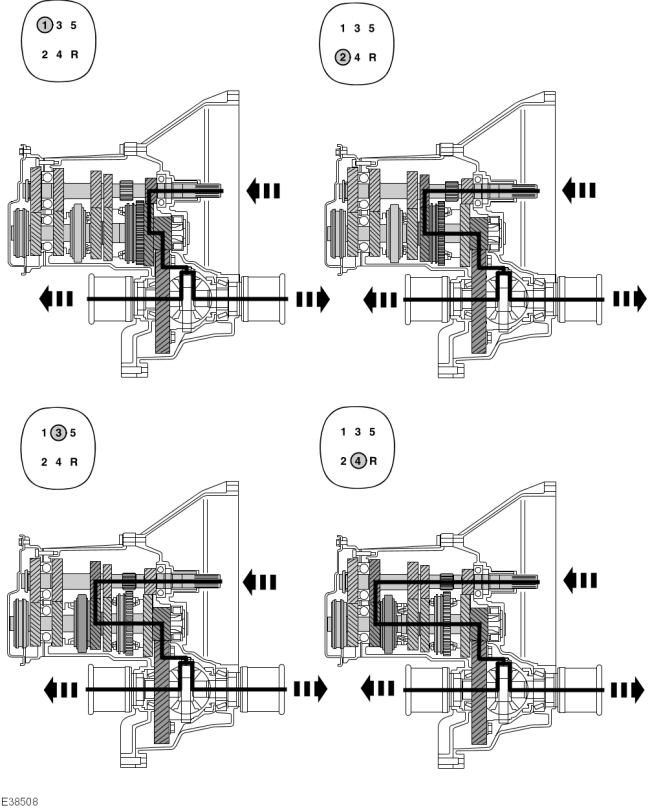
Power Transmission Route In 1st To 4th Gears
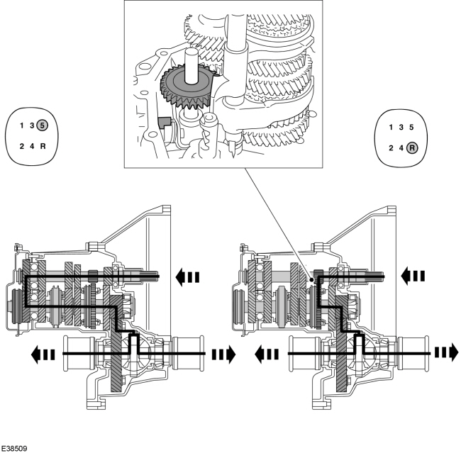
Power Transmission Route In 5th And Reverse Gears
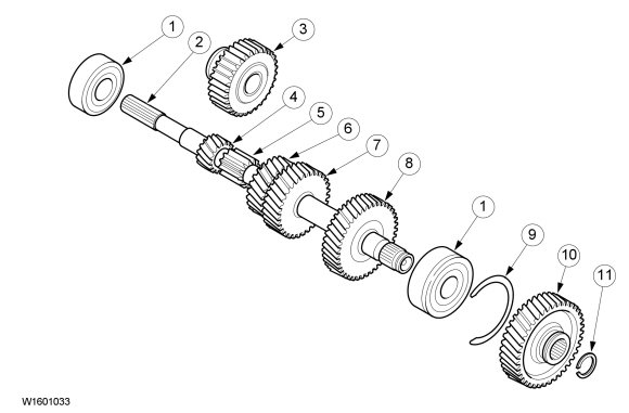
Input Shaft
| Item | Description |
|---|---|
| 1 | Ball bearing |
| 2 | Input Shaft |
| 3 | Reverse gear idler |
| 4 | 1st gear |
| 5 | Reverse gear |
| 6 | 2nd gear |
| 7 | 3rd gear |
| 8 | 4th gear |
| 9 | Snap ring |
| 10 | 5th gear |
| 11 | Snap ring |
The gears are located on the input shaft:
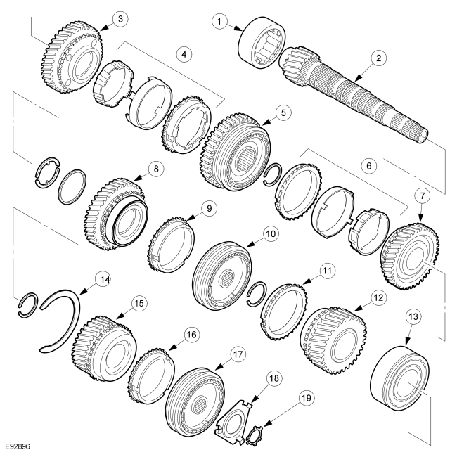
Output Shaft
| Item | Description |
|---|---|
| 1 | Roller bearing |
| 2 | Output shaft |
| 3 | 1st gear |
| 4 | 1st gear dual synchronizer |
| 5 | 1st/2nd gear synchronizer clutch with reverse gear |
| 6 | 2nd gear dual synchronizer |
| 7 | 2nd gear |
| 8 | 3rd gear |
| 9 | 3rd gear dual synchronizer |
| 10 | 3rd/4th gear synchronizer clutch |
| 11 | 4th gear single synchronizer |
| 12 | 4th gear |
| 13 | Ball bearing |
| 14 | Snap ring |
| 15 | 5th gear |
| 16 | 5th gear single synchronizer |
| 17 | 5th gear synchronizer assembly |
| 18 | Retaining plate
Comments: Not for transmissions with modified 5th gear synchronizer |
| 19 | Snap ring |
All gears of the manual transmission are on the output shaft.
The reverse gear is part of the 1st/2nd gear synchronizer clutch.
The output shaft is a hollow shaft through which transmission fluid flows. Bores in the hollow shaft ensure lubrication of the needle bearings and the synchronizer clutches.
An oil thrower behind the roller bearing (transmission housing side) ensures the necessary oil supply for the hollow shaft.
Dual Synchronizer
| Item | Description |
|---|---|
| 1 | Gear |
| 2 | Inner synchronizer ring |
| 3 | Conical ring |
| 4 | Outer synchronizer ring |
| 5 | Synchronizer hub |
1st and 2nd gears are dual synchronized.
The effective synchronization surface for dual synchronizer is almost twice that of single synchronizer. Because of this, the speeds of the gearwheels are equalized much faster, which considerably improves shifting comfort.
Reverse
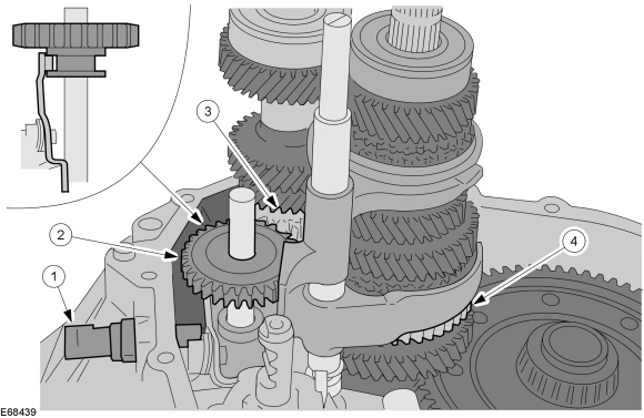
| Item | Description |
|---|---|
| 1 | Backup lamp switch |
| 2 | Reverse idler gear |
| 3 | Reverse drive gear |
| 4 | Reverse gear |
The reverse gear is permanently attached to the input shaft. The reverse gear is located on the output shaft.
The reverse idler gear runs freely in a bearing seat on the reverse idler gear shaft.
If the reverse gear is engaged, the reverse idler gear is moved in the axial direction. It is moved until the reverse gear, the reverse gear and the reverse idler gear engage. The direction of rotation of the output shaft is reversed when the three gears engage.
All three gears have straight-cut teeth.
The reverse gear switch is located at the side.
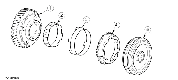
5th Gear Synchronizer
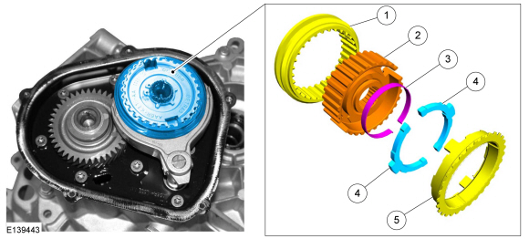
| Item | Description |
|---|---|
| 1 | Shift collar (5th gear) |
| 2 | Synchronizer (5th gear) |
| 3 | Spring washer |
| 4 | C-washer |
| 5 | Synchronizer ring (5th gear) |
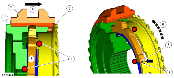
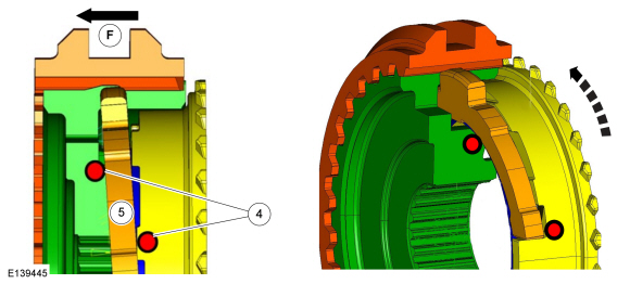
| Item | Description |
|---|---|
| F | Axial force |
| 1 | 5th gear synchronizer assembly |
| 2 | Shift collar (5th gear) |
| 3 | Synchronizer ring (5th gear) |
| 4 | C-washer abutment points |
| 5 | C-washer |
| 6 | Direction of rotation - output shaft |
| 7 | C-washer seating point |
| 8 | Synchronizer ring seating point |
Function Of The 5th Gear Synchronizer
The axial force of the selector rod moves the shift collar in the direction of 5th gear.
With the movement of the shift collar, the C-washer is pressed against the synchronizer ring ( upper abutment point ). At the same time, the C-washer is supported on the synchronizer clutch ( lower abutment point ).
Because of the pressure of the C-washer on the synchronizer ring, this is pressed against the conical friction surface of the gearwheel and thus the pre-synchronization starts.
As long as the shift collar and gearwheel rotate at different speeds, a turning torque is generated. This twists the synchronizer ring until the synchronizer ring abutment point touches the C-washer abutment point (arrow). The pre-synchronization is over.
After the complete synchronization process is finished, the shift collar moves over the splines of the synchronizer ring into the splines of the gearwheel. In the process, the two C-washers are pushed away inwards against the spring effect of the spring washer.
Engaging Reverse Gear
| Item | Description |
|---|---|
| F | Axial force |
| 4 | C-washer abutment points |
| 5 | C-washer |
Because of the shift construction of the transmission, the axial force of the selector rod moves the 5th gear shift collar in the opposite direction to the 5th gear gearwheel.
As a result of this, the C-washer is pressed against the synchronizer ring ( lower abutment point ). At the same time, the C-washer is supported on the synchronizer clutch ( upper abutment point ).
Because of the pressure of the C-washer on the synchronizer ring, this is pressed against the conical friction surface of the gearwheel. The synchronizer ring thereby presses against the conical friction surface of the gearwheel and in doing so slows down the input shaft .
This ensures that the speed of the transmission shafts is equal to zero while the reverse gear idler gear is inserted. The so-called 'crunch' during rapid engagement of reverse gear is thus prevented. The pre-requirement however is that the vehicle is no longer moving while reverse gear is being engaged.
Function Of Slowing The Input Shaft As Reverse Gear Is Engaged
The 5th gear synchronizer is firmly connected to the output shaft. The vehicle is stationary during engagement of reverse gear, whereby the output shaft does not turn. On the other hand, the input shaft with the gear for 5th gear and the 5th gear gearwheel on the output shaft rotate at engine speed. During the shift operation into reverse gear, the 5th gear synchronizer ring is briefly pressed against the 5th gear gearwheel and slows it down, whereby in turn the input shaft is slowed down.
Neutral Position
In the neutral position of the 5th gear synchronizer clutch, the C-washers are exactly perpendicular to the Y-axis. Consequently, there is also no pressure exerted on the synchronizer ring.
Differential Assembly
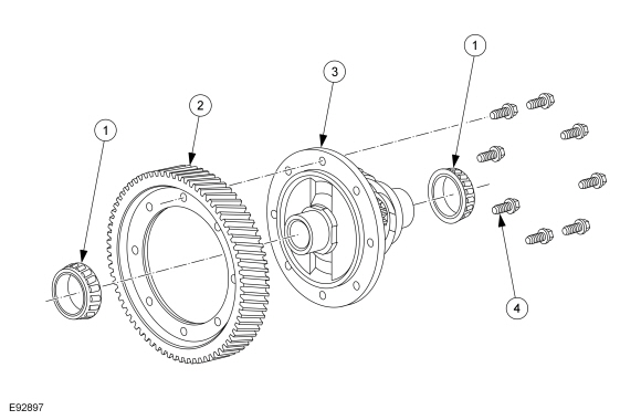
| Item | Description |
|---|---|
| 1 | Bearing |
| 2 | Ring gear |
| 3 | Differential assembly |
| 4 | Differential carrier bolts |
The differential assembly is built into the transmission housing.
The drive torque is transmitted to the differential by the differential carrier which is bolted to it.
The differential assembly contains differential pinion gears mounted on a spindle and the axle halfshaft pinion gears which connect to the front wheel axle halfshafts through helical gearing.
The axle halfshaft pinion gears can revolve around the differential pinion gears when the road wheel speeds are different (e.g when cornering).
Internal Shift Mechanism
Layout
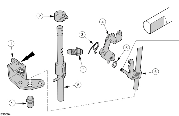
| Item | Description |
|---|---|
| 1 | Selector gate |
| 2 | Shift locking bush |
| 3 | Return spring from reverse gear position |
| 4 | Reverse gear selector shaft |
| 5 | Snap ring |
| 6 | Shift rod - 5th gear/reverse gear |
| 7 | Selector Interlock Mechanism |
| 8 | Selector shaft |
| 9 | Guide sleeve |
The shift locking bush prevents two gears from being engaged at the same time.
The selector interlock maintains engagement of the selected gear.
Both the shift and the select process is performed through the selector shaft.
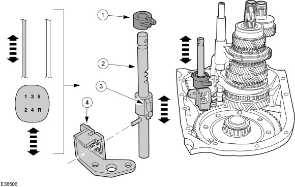
Select Movement
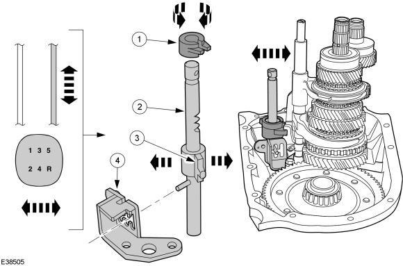
| Item | Description |
|---|---|
| 1 | Shift locking bush |
| 2 | Selector shaft |
| 3 | Selector finger |
| 4 | Selector gate |
The axial movement of the selector cable is transferred at the transmission to the selector shaft which can turn in its bearing.
If the gearshift lever is moved to the left or right, the selector shaft and the selector boss both turn together in the corresponding direction.
As this happens, the selector shaft is guided by a pin in the selector gate.
The selector boss selects the required selector fork.
At the same time the shift locking bush prevents access to other gear combinations.
Shift Movement
| Item | Description |
|---|---|
| 1 | Shift locking bush |
| 2 | Selector shaft |
| 3 | Selector finger |
| 4 | Selector gate |
After the gear pair to be shifted has been selected, the shift movement takes place.
Here the axial movement of the shift cable at the transmission produces an axial movement of the selector shaft.
If the gearshift lever is moved forwards or backwards, the selector shaft and the selector boss both move vertically together.
As this happens, the selector shaft is guided by a pin in the selector gate.
The selector boss shifts the required selector fork.
At the same time the shift locking bush prevents access to other gear combinations.
Engage Reverse Gear
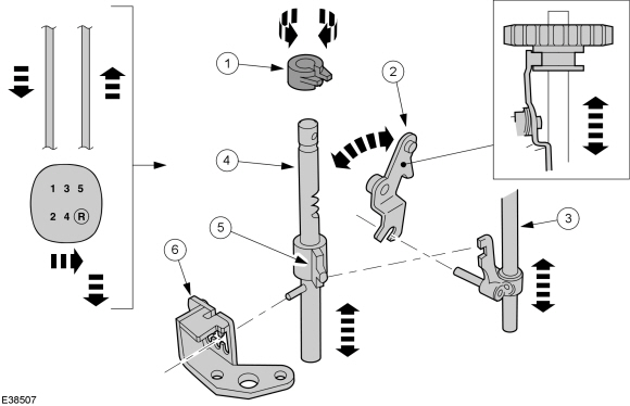
| Item | Description |
|---|---|
| 1 | Shift locking bush |
| 2 | Reverse gear selector shaft |
| 3 | Shift rod - 5th gear/reverse gear |
| 4 | Selector shaft |
| 5 | Selector finger |
| 6 | Selector gate |
In order to select reverse gear, the gearshift lever must be moved to the right over and past the reverse gear inhibit device. As this occurs the axial movement of the selector cable is transferred to the selector shaft which can turn in its bearing.
When shifting into reverse gear, the gearshift lever is moved backwards. The selector boss engages in the 5th gear/reverse gear shift rod, which in turn engages through a pin in the reverse gear selector shaft.
During the select and shift process the selector shaft is guided through the selector gate by a pin.
The reverse gear idler is slid by the reverse gear selector shaft and reverse gear is engaged.
At the same time the shift locking bush prevents access to other gear combinations.
Copyright © Ford Motor Company