| 414-00 Charging System - General Information | 2014 Fiesta |
| Description and Operation | Procedure revision date: 04/26/2013 |
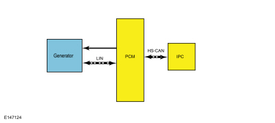
System Diagram
| Item | Description |
|---|---|
| 1 | Generator |
| 2 | PCM |
| 3 | IPC |
System Operation
Charging System
The PCM -controlled, or Smart Charge charging system determines the optimal voltage setpoint for the charging system and communicates this information to the voltage regulator. The Smart Charge charging system is designed to set a DTC any time a charging system fault is present. All of the Diagnostic Trouble Codes (DTCs) can set continuous faults, but not all Diagnostic Trouble Codes (DTCs) set as on-demand faults.
| Diagnostic Trouble Code (DTC) | Key ON Engine OFF (KOEO) | Key ON Engine Running (KOER) | Continuous |
|---|---|---|---|
| P0562 | X | X | X |
| P0563 | X | X | X |
| P065B | — | X | X |
| P065C | — | X | X |
| P0A3B | — | X | X |
| U012D | X | X | X |
| U042E | — | X | X |
Some of the Parameter Identifications (PIDs) and their associated descriptions used in the charging system diagnosis are listed below:
| PID | Description | Normal Display |
|---|---|---|
| GENMON | Generator Monitor | Constant fluctuating percentage 3%-98% |
| GENCMD | Generator Command | Fluctuating percentage or small intermittent bursts 3%-98% |
| GENVDSD | Generator Voltage Desired | Voltage varies by vehicle needs - May be controlled by an output state control |
| GENFIL | Generator Fault Indicator Lamp | OFF if charging system is OK |
| GENCMD_LF | Generator Command Line Fault | NO FAULT if GENCOM circuit (GENCMD PID ) is OK |
| GENMON_HZ | Generator Monitor Frequency | Frequency value |
| VPWR | Module Supply Voltage | Within 0.5 volt of battery voltage |
| RPM | Engine Revolutions Per Minute | Engine Revolutions Per Minute (RPM) - May be controlled by an output state control |
This system uses a dedicated LIN communication circuit. The generator uses this LIN circuit to communicate the desired setpoint from the PCM to the voltage regulator. The generator also uses this LIN circuit to communicate the generator load and error conditions to the PCM .
The PCM simultaneously controls and monitors the output of the generator. When the usage of current is high or the battery is discharged, the PCM raises engine speed as needed to increase generator output. The generator charges the battery and at the same time supplies power for all of the electrical loads that are required. The battery is more effectively charged with a higher voltage when the battery is cold and a lower voltage when the battery is warm. The PCM uses the measurement from the IAT sensor to adjust the charging voltage according to the battery temperature. The PCM also uses other inputs to control charging system voltage such as the Vehicle Speed Sensor (VSS) and ECT sensor. The voltage setpoint is calculated by the PCM and communicated to the voltage regulator by the LIN circuit based on the needs of the vehicle and the operating conditions.
The PCM turns off the generator during cranking to reduce the generator load and improve cranking speed. Once the engine starts, the PCM slowly increases generator output to desired voltage.
The
PCM
controls the charging system warning indicator by sending a message over the
HS-CAN
to the
IPC
. The
IPC
module turns the charging system warning indicator ON or OFF.The
IPC
will also send a message to the
FCDIM
(vehicles without Touch Screen display) or
FDIM
(vehicles with Touch Screen display) to display CHECK CHARGING SYSTEM. When the ignition is ON and the engine is off, the
CHECK CHARGING SYSTEM message may not be displayed. For additional information regarding the
IPC
module,
Refer to:
Message Center - System Operation and Component Description
(413-01 Instrumentation, Message Center and Warning Chimes, Description and Operation).
For additional information regarding the
FCDIM
or
FDIM
, Refer to the appropriate section in Group 415 for the procedure.
Under certain circumstances the charging system may have a concern but still keep the battery charged and the vehicle running. The LIN normally initiates charging from the PCM , but the generator may continue charging when a fault is present on this circuit. If the engine is operated at greater than 2,000 rpm momentarily, the generator may self-excite or start charging on its own. The charging system warning indicator is illuminated and/or CHECK CHARGING SYSTEM message is displayed, and the generator operates in a default mode (approximately 13.5 volts) until the engine is turned off. When the engine is restarted and the engine is operated at greater than 2,000 rpm momentarily, the generator may again self-excite and again the charging system warning indicator is illuminated and/or CHECK CHARGING SYSTEM message is displayed.
Component Description
Generator
The generator is driven by the FEAD drive belt. When the engine is started, the generator begins to generate AC voltage which is converted to DC voltage by the internal voltage regulator. The DC voltage is controlled by the voltage regulator and supplied to the battery. The PCM controls the voltage regulator set point, communicating with the generator internal voltage regulator over a dedicated LIN communication circuit.
Powertrain Control Module (PCM)
The PCM monitors and controls the charging system.
Copyright © Ford Motor Company