| 501-20B Supplemental Restraint System | 2014 Fiesta |
| Description and Operation | Procedure revision date: 05/15/2013 |
System Operation
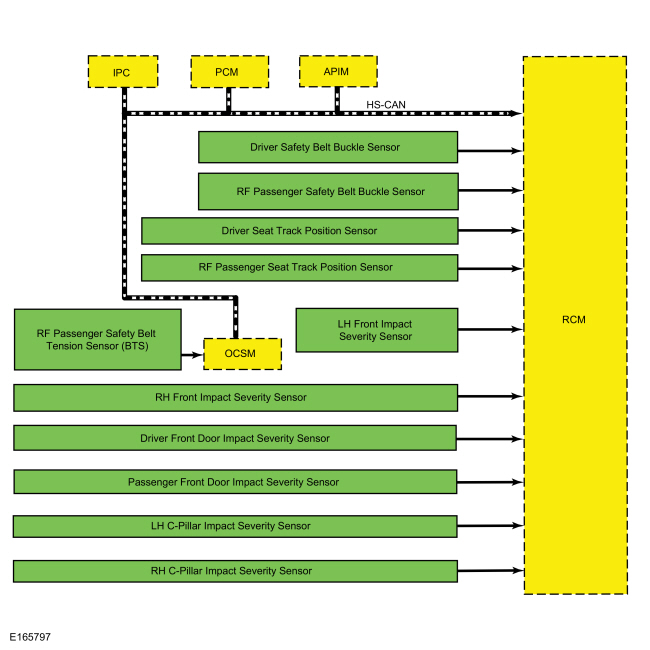
System Diagram - Supplemental Restraint System (SRS)
Network Message Chart - Supplemental Restraint System (SRS)
Module Network Input Messages - RCM
| Broadcast Message | Originating Module | Message Purpose |
|---|---|---|
| eCall confirmation | APIM | Used for SYNC® 911 Assist™ operation. Indicates whether eCall notification is in progress after an airbag deployment. |
| Ignition status | IPC | Used to qualify certain faults during RCM self-diagnostics. |
| Airbag warning indicator status | IPC | Confirms airbag warning indicator status to the RCM . |
| OCS calibration data | OCSM | Shares application-specific data for comparison purposes to make sure the correct OCSM and RCM are installed. |
| OCS fault status | OCSM | Indicates an OCS fault, if present. |
| OCS sensor data | OCSM | OCS sensor readings. |
| OCS serial number | OCSM | OCSM serial number. |
| Vehicle configuration data | IPC | Used for verifying vehicle configuration data. |
| Vehicle identification data | PCM | Used for verifying that the RCM is installed in the correct vehicle. |
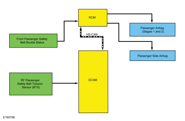
System Diagram - Occupant Classification System (OCS)
Network Message Chart - Occupant Classification System (OCS)
Module Network Input Messages
| Broadcast Message | Originating Module | Message Purpose |
|---|---|---|
| Passenger safety belt buckle status | RCM | Used for determining passenger airbag disable status. |
| RCM serial number | RCM | RCM serial number. |
Supplemental Restraint System
The SRS is controlled by the RCM , which continually monitors various inputs. When these inputs indicate a frontal or side crash, the RCM may deploy some components, based upon the severity of the crash and the sensor inputs.
Although some deployable devices may not have activated for all occupants during a crash, it does not mean that something is wrong with the SRS .
The RCM performs a self-test of the complete SRS during each startup. In addition to the self-test at start up, the RCM continuously monitors all of its SRS components and circuitry for correct operation.
Airbag Warning Indicator
The airbag warning indicator:
When the ignition is turned ON during normal operation, the IPC illuminates the airbag warning indicator continuously for 6 seconds. If the SRS is free of faults, the airbag warning indicator turns off and remains off. If a SRS fault exists, the airbag warning indicator illuminates and remains illuminated for the rest of the ignition cycle. The RCM communicates with the IPC via the HS-CAN . The IPC illuminates the airbag warning indicator based on messaging from the RCM . The IPC also illuminates the airbag warning indicator if there is no communication between the RCM and IPC .
Secondary Airbag Warning
A secondary airbag warning message is controlled by the IPC and displayed in the message center. If the RCM detects a SRS fault, the RCM sends a message via HS-CAN to the IPC . The IPC then illuminates the airbag warning indicator. If the IPC detects a fault with the airbag warning indicator, a DTC is stored in the IPC , then a warning message is displayed in the message center to indicate that a SRS fault is present.
Event Notification Signal
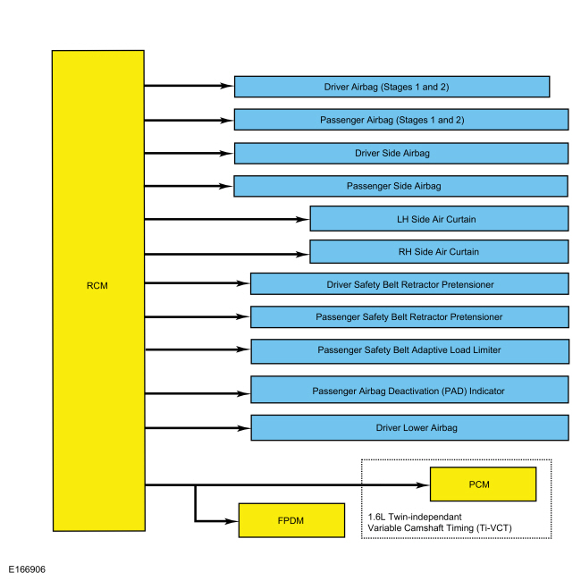
The event notification feature provides other vehicle subsystems with information pertaining to SRS deployment or fuel cutoff status. When an impact occurs which exceeds a pre-determined threshold, the RCM sends a signal on a dedicated circuit to the FPDM . On vehicles equipped with a 1.6L Twin-independant Variable Camshaft Timing (Ti-VCT) engine, the PCM also receives this signal.
For all vehicles, when the FPDM receives the crash signal input, it initiates fuel cutoff to disable the fuel system.
After the fuel system is disabled, the vehicle can be re-started after carrying out the following steps:
Occupant Classification System (OCS)
The OCS classifies the size of the front passenger seat occupant and provides this information to the RCM .
Pressure is applied to the OCS bladder when weight of any occupant or object in the front passenger seat is present. The pressure is then transferred through a tube and sensed by the OCS pressure sensor within the OCSM . The OCSM sends information concerning the weight of any occupant or object on the front passenger seat to the RCM via the HS-CAN . The RCM uses this information when determining if the passenger airbag or side airbag needs to be deployed in the event of a crash.
The
OCS
is also used for operation of the passenger Belt-Minder®.
Refer to:
Safety Belt System - System Operation and Component Description
(501-20A Safety Belt System, Description and Operation).
To deactivate or reactivate the passenger Belt-Minder® feature, Refer to:
Safety Belt Minder Deactivating/Activating
(413-01 Instrumentation, Message Center and Warning Chimes, General Procedures).
Passenger Airbag Deactivation (PAD) Indicator
The RCM controls the PAD indicator through a direct, hard-wired connection, based on information provided by the OCS . The PAD indicator illuminates to indicate the passenger airbag is disabled. An exception to this is when the front passenger seat is determined to be empty and indication of a deactivated passenger airbag is not necessary. In all other cases, the PAD indicator is off when the passenger airbag is enabled.
The RCM briefly activates the PAD indicator to prove out the indicator function and verify proper functional operation of the PAD indicator to the front occupants.
The following table indicates the passenger airbag and PAD indicator status based on the size of the front passenger occupant.
| Occupant Size | Passenger Safety Belt Buckle Status | Passenger Airbag Status | PAD Indicator Status |
|---|---|---|---|
| Empty | Unbuckled | Disabled | Unlit |
| Empty | Buckled | Disabled | Lit |
| Small | Buckled or Unbuckled | Disabled | Lit |
| Large | Buckled or Unbuckled | Enabled | Unlit |
Airbag Second Stage Deployment Check
The driver and passenger front airbags each have 2 deployment stages. After an airbag deployment, it is possible that stage
1 has deployed and stage 2 has not. If a front airbag has deployed, the front airbag must be remotely deployed using the appropriate
airbag disposal procedure to make sure both stages have been deployed. For information on driver airbag and/or passenger airbag
remote deployment,
Refer to:
Pyrotechnic Device Disposal
(501-20B Supplemental Restraint System, General Procedures).
SOS Post-Crash Alert System™
The SOS Post-Crash Alert System™ is controlled by the BCM , but initiated by the RCM .
When a deployment or fuel cutoff event occurs, the
RCM
sends a message on the
HS-CAN
to the
IPC
, which acts as a gateway and relays the message via the
MS-CAN
to the
BCM
. The
BCM
flashes the turn signal lamps and sounds the horn (except when 911 Assist™ is active) until it is turned off. The system
can be turned off 10 seconds after a crash event by pressing the hazard switch. The
BCM
also unlocks the doors after a crash event.
Refer to:
Module Controlled Functions - System Operation and Component Description
(419-10 Multifunction Electronic Modules, Description and Operation).
Component Description
Front Impact Severity Sensor
The front impact severity sensors measure acceleration (g-rate) and are hardwired to the RCM . Mounting orientation is critical for correct operation of the front impact severity sensors.
Occupant Classification System (OCS)
The OCS is found only on the front passenger seat. The OCS classifies the size of the front passenger seat occupant.
The OCS is comprised of a silicone gel-filled bladder mounted between the seat cushion foam and pan, an OCSM which is mounted to the seat frame, and a pressure sensor that is internal to the OCSM . Pressure is applied to the OCS bladder when weight of any occupant or object in the front passenger seat is present. The pressure is then transferred through a tube and sensed by the OCS pressure sensor and OCSM . The components of an OCS bladder system (bladder, tube, and OCSM with integrated pressure sensor) are serviced as an assembly, and the OCS bladder system is serviced as a kit with the seat cushion and seat heater mat (if applicable).
The Belt Tension Sensor (BTS) is a Hall-effect sensor that modifies a reference voltage supplied by the OCSM . As the amount of tension applied to the belt varies, so does the voltage that returns to the OCSM . The Belt Tension Sensor (BTS) is part of the front passenger safety belt anchor and can only be serviced with the front passenger safety belt retractor and pretensioner.
Safety Belt Buckle Sensor
The safety belt buckles contain integrated sensors that are Hall-effect switches. The safety belt buckle sensors are serviced with the safety belt buckle.
Safety Belt Tension Sensor (BTS)
The safety Belt Tension Sensor (BTS) is a 3-wire Hall-effect sensor that is part of the front passenger safety belt retractor and cannot be serviced separately from the front passenger safety belt retractor assembly.
Seat Position Sensor
The seat position sensor is a Hall-effect sensor which indicates the position of the seat along the seat track. The sensor detects the presence of a shunt bracket on the track, indicating the seat has moved past a certain point in the adjustment range.
Side Impact Sensor - C-pillar
The C-pillar side impact sensors measure acceleration (g-rate), and are hardwired to the RCM . Mounting orientation is critical for correct operation of the C-pillar side impact sensors.
Side Impact Sensor - Front Door
The front door side impact sensors measure air pressure within the door in order to detect certain crashes, such as a side impact. Mounting position and orientation is critical for correct operation of the front door side impact sensors.
Driver Airbag
The driver airbag is a dual-stage airbag. Upon receiving a flow of current, it deploys at 1 of 2 different rates, depending upon vehicle impact severity and sensor input.
Passenger Airbag
The passenger airbag is a dual-stage airbag which deploys at 1 of 2 different rates depending upon vehicle impact severity and sensor input.
Passenger Airbag Deactivation (PAD) Indicator
The PAD indicator is a LED which is hardwired to the RCM .
Safety Belt Retractor and Adaptive Load Limiter
The front passenger safety belt retractor is equipped with the adaptive load limiting feature that works in conjunction with the safety belt retractor pretensioner to control the tension of the front passenger safety belt in the event of a crash. The front passenger safety belt retractor is also referred to as the seatbelt load limiter.
To diagnose any adaptive load limiter Diagnostic Trouble Codes (DTCs),
Refer to:
Airbag Supplemental Restraint System (SRS)
(501-20B Supplemental Restraint System, Diagnosis and Testing).
For any concerns regarding safety belt retractor function:
Refer to:
Safety Belt System
(501-20A Safety Belt System, Diagnosis and Testing).
Safety Belt Retractor and Pretensioner
The safety belt retractor and pretensioner is a pyrotechnic device that removes excess webbing from the safety belts when deployed.
To diagnose any pretensioner Diagnostic Trouble Codes (DTCs):
Refer to:
Airbag Supplemental Restraint System (SRS)
(501-20B Supplemental Restraint System, Diagnosis and Testing).
For any concerns regarding safety belt retractor function:
Refer to:
Safety Belt System
(501-20A Safety Belt System, Diagnosis and Testing).
Side Air Curtain
The side air curtain is a single-stage airbag which is designed to protect the vehicle occupant(s) during certain side impact crashes.
Side Airbag
The side airbag is a single-stage airbag which deploys upon receipt of current flow during certain side impact crashes. It is attached to the outboard side of each front seat and is used in conjunction with the side air curtain.
Driver Lower Airbag
The driver lower airbag is a single-stage airbag which deploys upon receipt of current flow.
Clockspring
The clockspring allows for continuous electrical connections between the driver airbag and the RCM . A spiral-wound cable wraps around the center of the clockspring and as the steering wheel is turned, the spiral cable inside expands or contracts in diameter as the 2 halves of the clockspring turn.
Restraints Control Module (RCM)
NOTE: This vehicle may be equipped with SYNC®, which contains the 911 Assist™ option. Refer to the Owner's Literature for information about this feature.
The RCM monitors various sensor inputs and uses that data for controlling SRS outputs such as Belt-Minder® function and airbag deployment.
The RCM includes a backup power supply. This feature provides sufficient backup power to deploy the airbags in the event the ignition circuit is lost or damaged during impact. The backup power supply depletes its stored energy approximately one minute after power and/or ground has been removed from the RCM .
The RCM requires PMI when being replaced. Refer to the diagnostic scan tool instructions to carry out PMI .
Copyright © Ford Motor Company