 WARNING:
Before beginning any service procedure in this section, refer to Safety Warnings in section 100-00 General Information. Failure
to follow this instruction may result in serious personal injury.
WARNING:
Before beginning any service procedure in this section, refer to Safety Warnings in section 100-00 General Information. Failure
to follow this instruction may result in serious personal injury.
| 204-04A Wheels and Tires | 2014 Fiesta |
| Disassembly and Assembly | Procedure revision date: 05/2/2013 |
DISASSEMBLY
NOTICE: Failure to follow the instructions below may result in damage to the TPMS sensor.
NOTICE: The TPMS sensor is mounted to the valve stem. Removal of the valve stem requires dismounting the tire from the wheel and removal of the TPMS sensor.
NOTE: Use only the Digital Tire Pressure Gauge any time tire pressures are measured to be sure that accurate values are obtained.
WARNING:
Before beginning any service procedure in this section, refer to Safety Warnings in section 100-00 General Information. Failure
to follow this instruction may result in serious personal injury.
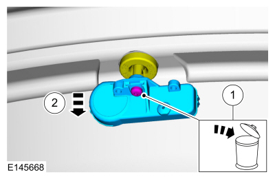
NOTICE: The TPMS sensor is connected to the valve stem. Do not pull the valve stem from the wheel, or damage to the sensor will occur.
NOTE: If a new TPMS sensor is being installed, remove and discard the valve stem-to-sensor screw and the sensor.
Remove the valve stem core and fully deflate all air from the tire.NOTICE: Do not allow the tire beads to move beyond the wheel mid-plane (middle of the wheel) when separating the beads from the wheels, damage to the TPMS sensor may occur.
NOTICE: Tire and valve stem position is critical to prevent damage to the TPMS sensor when using a paddle-type bead separator.
NOTE:
Some machines may have a nylon roller bead separator at the 12 o'clock position instead of the paddle-type bead separator
at the 3 o'clock position.
NOTE: Paddle type shown, roller type similar.
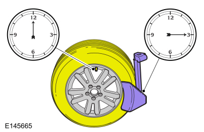

NOTE: Index-mark the valve stem and wheel weight positions on the tire.
Place the wheel and tire assembly on the turntable of the tire machine with the valve stem at the 11:30 position and the machine arm at the 12 o'clock position and dismount the outer bead from the wheel.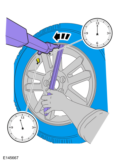
NOTE: A new valve stem must be installed whenever a new tire or wheel is installed.
NOTICE: Use care not to damage the wheel surface when removing the valve stem.
General Equipment : Wooden Block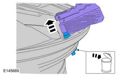
NOTICE: To prevent TPMS sensor and valve stem damage, the valve stem must be installed onto the TPMS sensor and then installed into the wheel as an assembly.
NOTE: When installing a new wheel, always install a new valve stem and sensor screw. Reuse the TPMS sensor from the previous wheel if possible. The TPMS will not have to be trained if the sensor is reused.
NOTE: If the TPMS sensor is being reused, inspect the TPMS sensor for damage and install a new sensor as necessary.
Torque : 1.5 Nm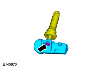
ASSEMBLY
NOTICE: Damage to the TPMS sensor may result if the tire mounting is not carried out as instructed.
NOTICE: Use care not to damage the wheel surface when installing the valve stem and TPMS sensor assembly.
NOTE: Lubricate the valve stem with soapy water and install the valve stem and TPMS sensor assembly into the wheel using a block of wood and a suitable valve stem installer.
General Equipment : Wooden Block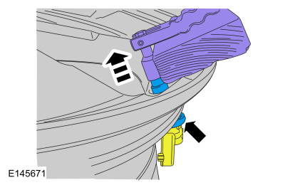
NOTE: Lubricate the tire beads using a suitable fast-drying, corrosion-inhibiting tire bead lubricant.
NOTE: Do not mount the tire at this time.
Position the wheel on the turntable of the tire machine, then lubricate and position the bottom bead of the tire on the wheel.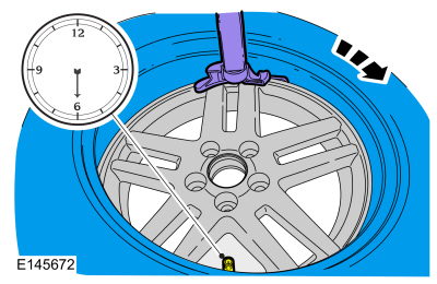
NOTE: Use only the Digital Tire Pressure Gauge any time tire pressures are measured to be sure that accurate values are obtained.
Inflate the tire to the pressure specified on the VC label located on the driver door or door pillar.NOTE: Proceed to the next step if the tire beads do not seat at the specified inflation pressure.
WARNING:
If there is a need to exceed the maximum pressure indicated on the sidewall of the tire in order to seat the beads, follow
all steps listed below. Failure to follow these steps may result in serious personal injury.
NOTICE: The following steps should only be carried out if the tire beads cannot be seated by inflating the tire up to the maximum inflation pressure listed on the tire sidewall.
Copyright © Ford Motor Company