 WARNING:
Before beginning any service procedure in this manual, refer to health and safety warnings in section 100-00 General Information.
Failure to follow this instruction may result in serious personal injury.
WARNING:
Before beginning any service procedure in this manual, refer to health and safety warnings in section 100-00 General Information.
Failure to follow this instruction may result in serious personal injury.
| 303-01A Engine - 1.6L Duratec-16V Ti-VCT (88kW/120PS) - Sigma | 2014 Fiesta |
| Assembly | Procedure revision date: 05/2/2013 |
All vehicles
NOTICE: During engine repair procedures, cleanliness is extremely important. Any foreign material, including any material created while cleaning gasket surfaces that enters the oil passages, coolant passages or the oil pan, can cause engine failure.
NOTE: Refer to exploded views in Description and Operation.
WARNING:
Before beginning any service procedure in this manual, refer to health and safety warnings in section 100-00 General Information.
Failure to follow this instruction may result in serious personal injury.

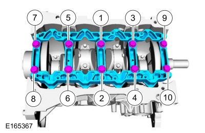
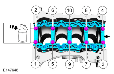
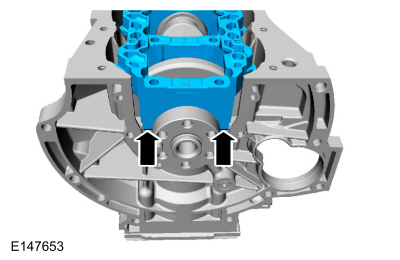
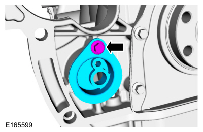
NOTE: The main bearing beam has 2 arrows pointing towards the front of engine for correct orientation for reassembly.
Mounted flush and finger tight.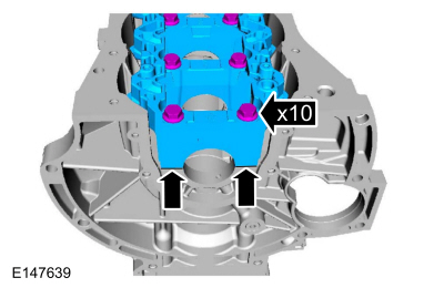
NOTICE: The rod cap installation must keep the same orientation as marked during disassembly or engine damage may occur.
Use the original connecting rod cap bolts.
NOTE: Before assembling the cylinder block, all sealing surfaces must be free of chips, dirt, paint and foreign material. Also, make sure the coolant and oil passages are clear.
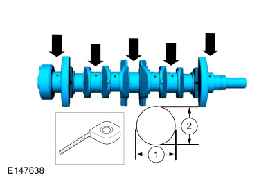
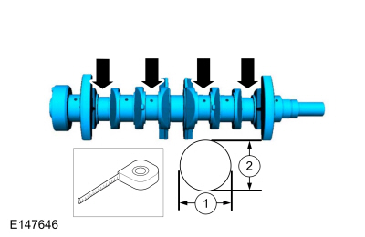
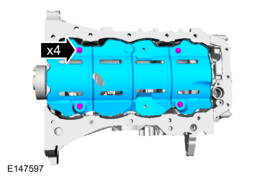
NOTE: If reusing the crankshaft main bearings, install them in their original positions and orientation as noted during disassembly.
Material : Motorcraft® SAE 5W-20 Premium Synthetic Blend Motor Oil / XO-5W20-QSP (WSS-M2C945-A)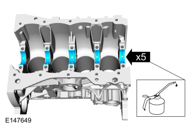
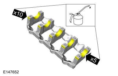
NOTE: If reusing the crankshaft main bearings, install them in their original positions and orientation as noted during disassembly.
Material : Motorcraft® SAE 5W-20 Premium Synthetic Blend Motor Oil / XO-5W20-QSP (WSS-M2C945-A)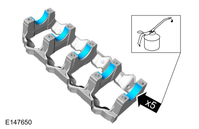
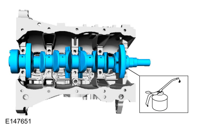
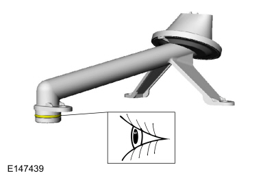
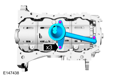
NOTE: Lubricate the main bearing beam bolts threads with clean engine oil.
NOTE: Position the crankshaft to the rear of the cylinder block, then position the crankshaft to the front of the cylinder block before tightening the main bearing beam bolts.
Material : Motorcraft® SAE 5W-20 Premium Synthetic Blend Motor Oil / XO-5W20-QSP (WSS-M2C945-A)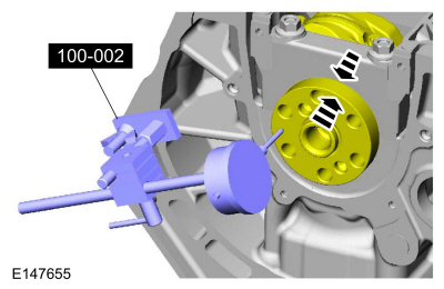
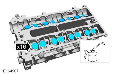
NOTE: If reusing the connecting rod bearings, install them in their original positions and orientation as noted during disassembly.
NOTE: Make sure the dimple faces the front of the engine.
Material : Motorcraft® SAE 5W-20 Premium Synthetic Blend Motor Oil / XO-5W20-QSP (WSS-M2C945-A)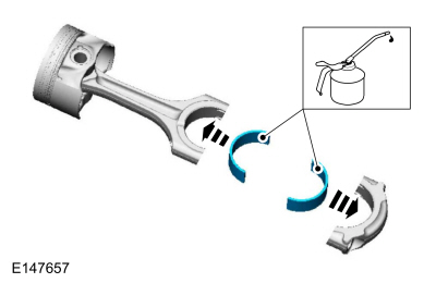
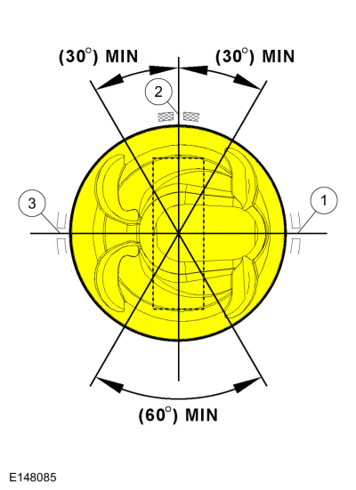
NOTE: The upper and lower compression rings are to be fitted with the identification marks on the upper side.
NOTE: The upper and lower compression ring end gaps are not controlled for installation.
NOTE: Using a connecting rod installer will unsure not to scratch the cylinder wall or crankshaft journal with the connecting rod. Push the piston down until the connecting rod bearing seats on the crankshaft journal.
NOTE: Make sure the piston arrow on top is facing toward the front of the engine.
General Equipment : Piston Ring Compressor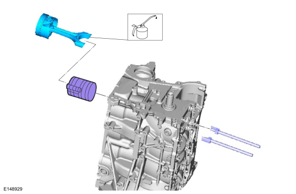
NOTICE: The rod cap installation must keep the same orientation as marked during disassembly or engine damage may occur.
NOTE: Install connecting rod caps and bolts on the connecting rods for cylinders 1 and 4 first and tighten. Then rotate crankshaft 180 degrees and install connecting rod caps and bolts on connecting rods for cylinders 2 and 3 and tighten.
NOTE: After installation of each connecting rod cap, rotate the crankshaft to verify smooth operation.
Use new connecting rod caps bolts.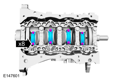
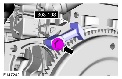
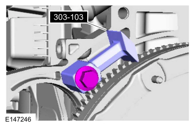
NOTE: Only rotate the crankshaft clockwise direction.
Rotate the crankshaft until the crankshaft balance weight is up against the crankshaft locking tool. The engine is now at TDC .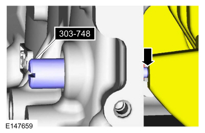
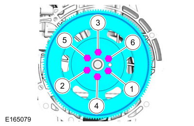
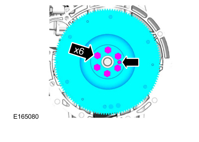
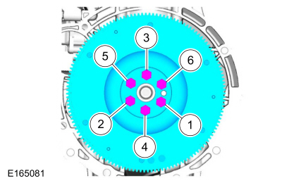
NOTE: There are different length of bolts noted in disassembly.
Torque :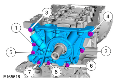
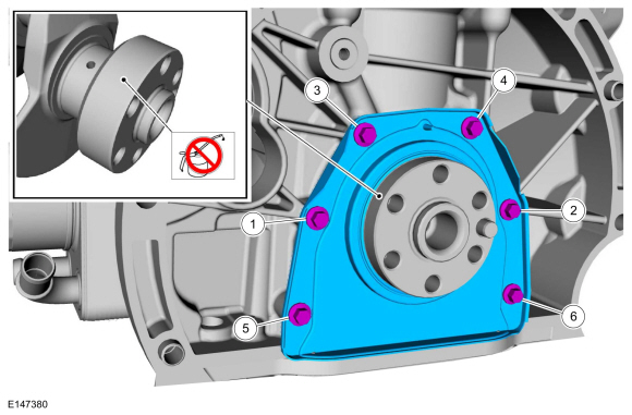
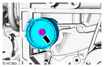
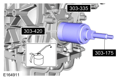
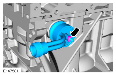
NOTE: The O-ring seal is to be reused unless damaged.
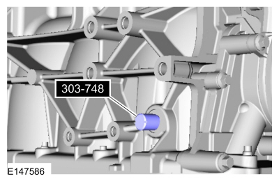
NOTE: New crankshaft rear seal is supplied with an alignment sleeve which must be removed after installation.
NOTE: Do not remove the alignment sleeve from the crankshaft rear seal prior to installation on the crankshaft.
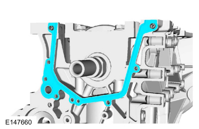
NOTICE: Do not use metal scrapers, wire brushes, power abrasive discs or other abrasive means to clean the sealing surfaces. These tools cause scratches and gouges, which make leak paths. Use a plastic scraping tool to remove traces of sealant.
Make sure that the mating faces are clean and free of foreign material.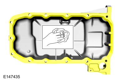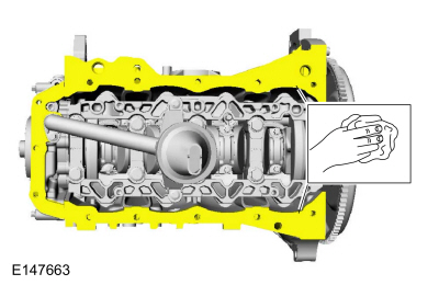
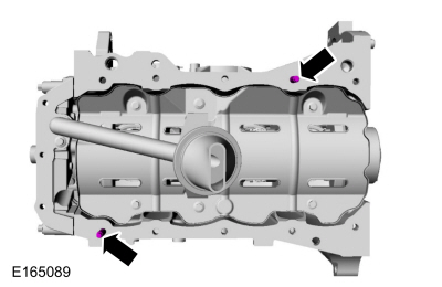
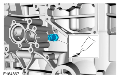
NOTE: The component must be installed within 5 minutes of applying the sealant.
Material : Silicone Gasket and Sealant / TA-30 (WSE-M4G323-A4)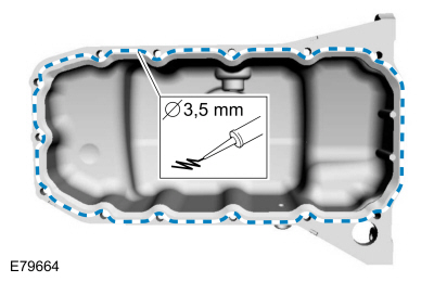
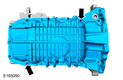
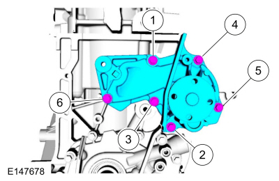
NOTE: Only tighten the bolts finger tight at this stage.
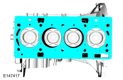
NOTICE: Do not use metal scrapers, wire brushes, power abrasive discs or other abrasive means to clean the sealing surfaces. These tools cause scratches and gouges that make leak paths. Use a plastic scraping tool to remove all traces of the head gasket.
NOTE: If there is no residual gasket material present, metal surface prep can be used to clean and prepare the surfaces.
Material : Motorcraft® Metal Surface Prep / ZC-31-A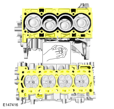
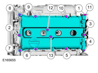
NOTE: The cylinder head bolts are torque-to-yield and must not be reused. New cylinder head bolts must be installed.
NOTE: Lubricate the bolts with clean engine oil prior to installation.
Material : Motorcraft® SAE 5W-20 Premium Synthetic Blend Motor Oil / XO-5W20-QSP (WSS-M2C945-A)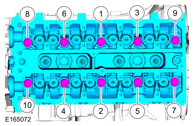
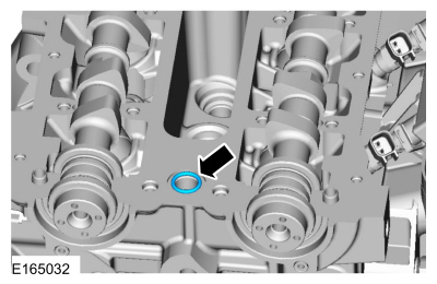
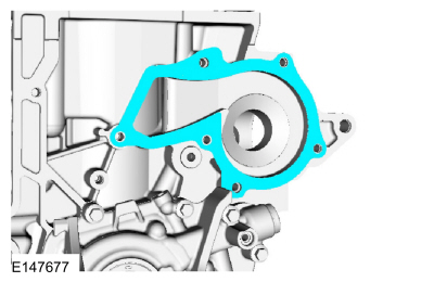
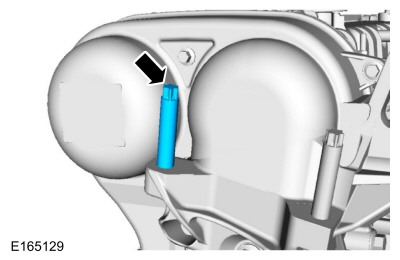
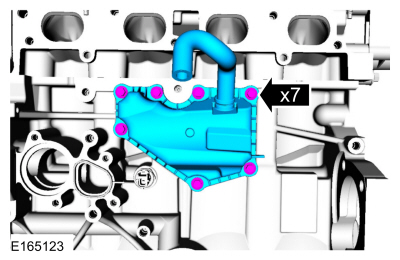
NOTE: The VCT bridge must be installed within 5 minutes of applying the gasket maker.
Material : Flange Sealant / CU7Z-19B508-A (WSS-M2G348-A11)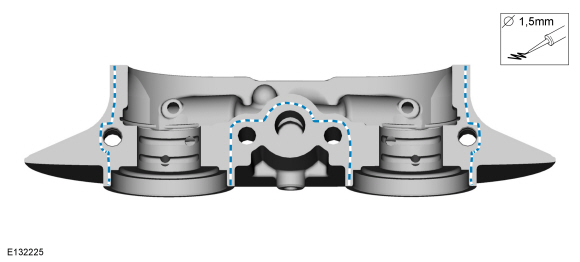
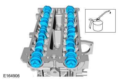
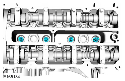
NOTE: Make sure that the camshafts and the camshaft bearing caps are installed in their original locations or damage to the engine may occur.
NOTE: Apply clean engine oil to the camshaft bearing caps and the VCT bridge.
Tighten the bolts evenly, half a turn at a time, until the camshaft bearing caps and the VCT bridge are seated against the cylinder head.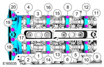
NOTE: It may be necessary to use an open-ended wrench to turn the camshafts by the hexagon to align the camshafts.
Install Special Service Tool : 303-376B Alignment Plate, Camshaft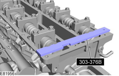
NOTE: Use an open-ended wrench to hold the camshafts by the hexagon to prevent the camshafts from turning.
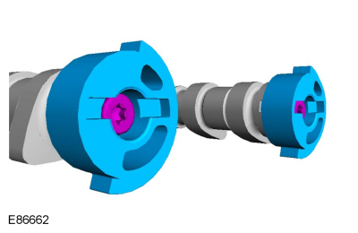
NOTE: The timing marks of the camshaft phaser and sprocket must be at the 12 o'clock position.
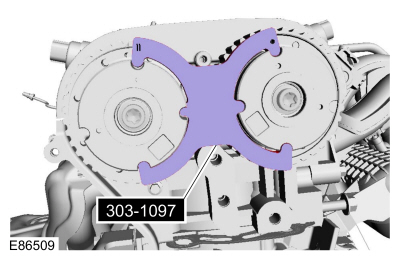
Install Special Service Tool : 303-1097 Locking Tool, Variable Camshaft Timing Oil Control Unit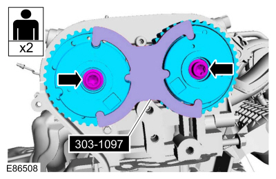
NOTE: Use an open-ended wrench to hold the camshafts by the hexagon to prevent the camshafts from turning.
Torque : Tighten an additional 75°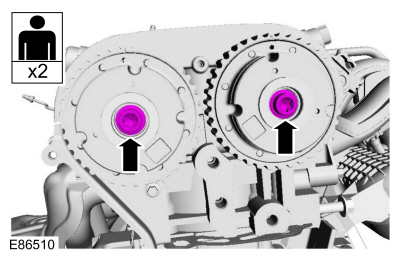
NOTE: The special tool can only be installed if the valve timing is correct.
Install Special Service Tool : 303-376B Alignment Plate, CamshaftNOTE: The special tool can only be installed if the valve timing is correct.
If the special tools cannot be installed, repeat the adjustment according to the preceding steps.NOTE: Use an open-ended wrench to hold the camshafts by the hexagon to prevent the camshafts from turning.
Torque : 16 Nm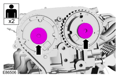
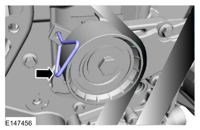
WARNING:
The timing belt tensioner spring is under load. Extra care must be taken at all times when handling the tensioner. Failure
to follow this instruction may result in personal injury.
WARNING:
The timing belt tensioner spring is under load. Extra care must be taken at all times when handling the tensioner. Failure
to follow this instruction may result in personal injury.
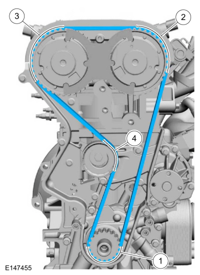
NOTE: Only rotate the crankshaft in a clockwise direction.
Rotate about 1 3/4 turns.
NOTE: Only rotate the crankshaft in a clockwise direction.
Rotate the crankshaft until the crankshaft balance weight is up against the crankshaft locking tool. The engine is now at TDC .NOTE: It may necessary to rotate the camshafts slightly to install the special tool.
NOTE: The special tool can only be installed if the valve timing is correct.
If the special tool cannot be installed, repeat the adjustment according to the preceding steps.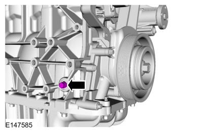
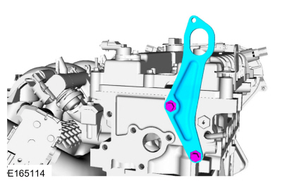
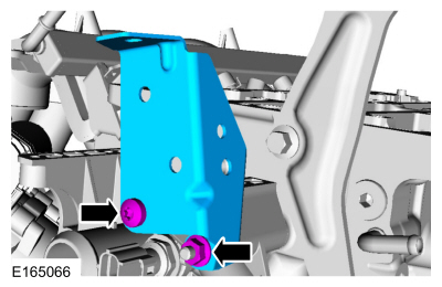
NOTE: There are different length of bolts noted in disassembly.
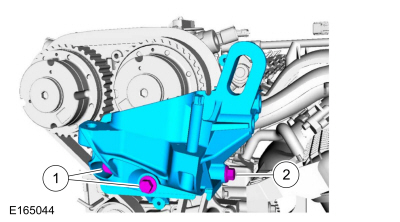
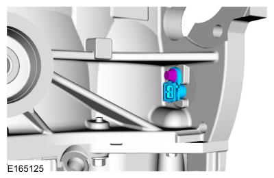
NOTICE: The 2 engine mount studs must be torqued or damage to the powertrain mount may occur.
Torque : 8 Nm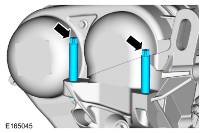
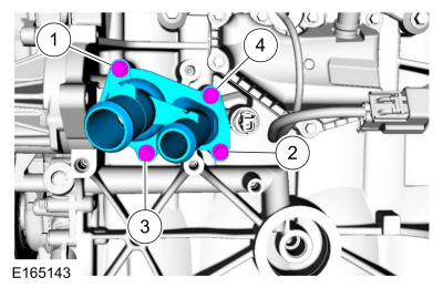
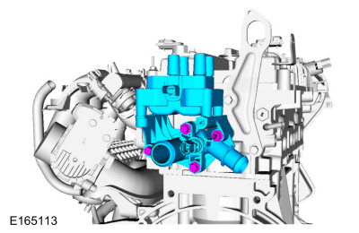
NOTE: The O-ring seals are to be reused unless damaged.
Material : Motorcraft® SAE 5W-20 Premium Synthetic Blend Motor Oil / XO-5W20-QSP (WSS-M2C945-A)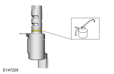
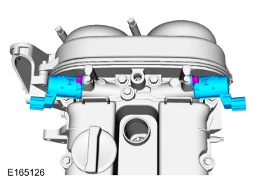
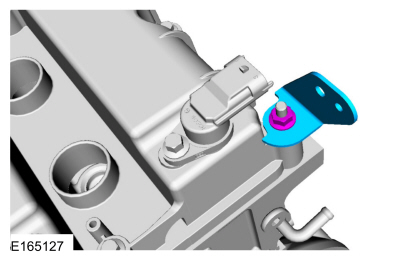
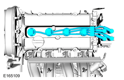
NOTE: The head of the KS should not touch any other component.
NOTE: The LH KS must be at the 11 o'clock position and the RH KS must be at the 2 o'clock position.
Torque : 18 Nm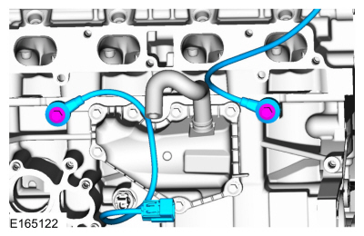
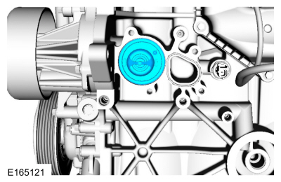
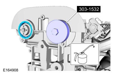
NOTICE: A new oil cooler must be installed or severe damage to the engine can occur.
Torque : 55 Nm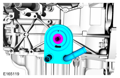
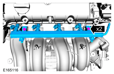
NOTICE: If the engine is repaired or replaced because of upper engine failure, typically including valve or piston damage, check the intake manifold for metal debris. If metal debris is found, install a new intake manifold. Failure to follow these instructions can result in engine damage.
Inspect and install new intake gaskets if necessary.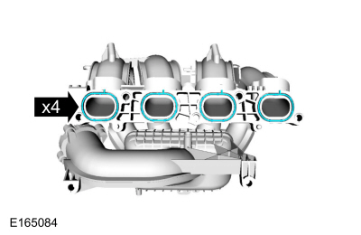
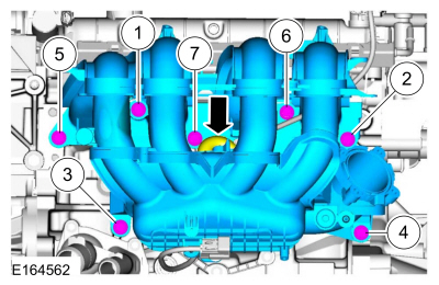
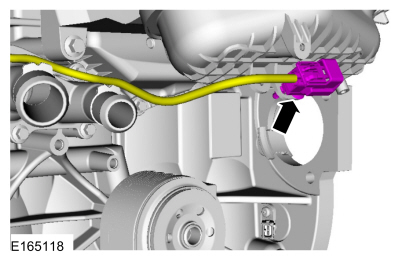
NOTE: Use O-rings that are made of special fuel-resistant material. The use of ordinary O-rings may cause the fuel system to leak. Do not reuse the O-ring seals.
Material : Motorcraft® SAE 5W-20 Premium Synthetic Blend Motor Oil / XO-5W20-QSP (WSS-M2C945-A)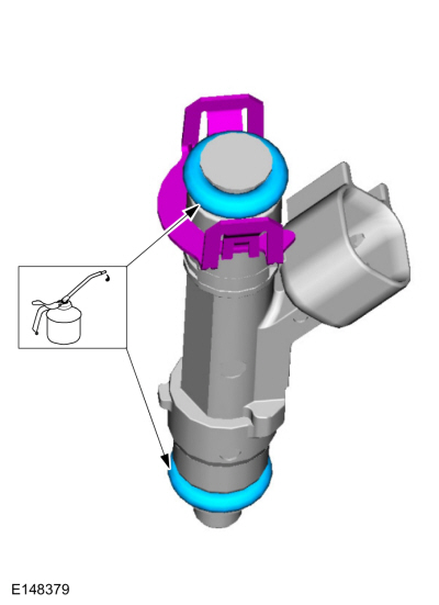
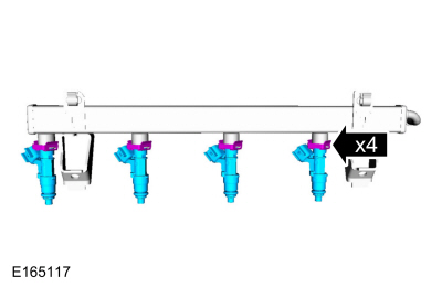
NOTE: Lubricate the O-ring seal with clean engine oil.
Material : Motorcraft® SAE 5W-20 Premium Synthetic Blend Motor Oil / XO-5W20-QSP (WSS-M2C945-A)
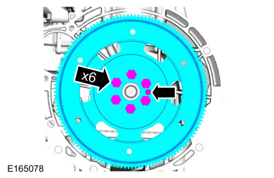
Vehicles with automatic transmission
Vehicles with manual transmission
NOTICE: Do not breathe dust or use compressed air to blow dust from storage containers or friction components. Remove dust using government-approved techniques. Friction component dust may be a cancer and lung disease hazard. Exposure to potentially hazardous components may occur if dusts are created during repair of friction components, such as brake pads and clutch discs. Exposure may also cause irritation to skin, eyes and respiratory tract, and may cause allergic reactions and/or may lead to other chronic health effects. If irritation persists, seek medical attention or advice. Failure to follow these instructions may result in serious personal injury.
Using a clutch aligner, centralize the clutch disc to the clutch pressure plate.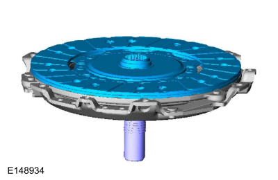
NOTICE: Do not breathe dust or use compressed air to blow dust from storage containers or friction components. Remove dust using government-approved techniques. Friction component dust may be a cancer and lung disease hazard. Exposure to potentially hazardous components may occur if dusts are created during repair of friction components, such as brake pads and clutch discs. Exposure may also cause irritation to skin, eyes and respiratory tract, and may cause allergic reactions and/or may lead to other chronic health effects. If irritation persists, seek medical attention or advice. Failure to follow these instructions may result in serious personal injury.
Torque : 29 Nm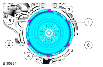
Copyright © Ford Motor Company