 WARNING:
Before beginning any service procedure in this section, refer to Safety Warnings in section 100-00 General Information. Failure
to follow this instruction may result in serious personal injury.
WARNING:
Before beginning any service procedure in this section, refer to Safety Warnings in section 100-00 General Information. Failure
to follow this instruction may result in serious personal injury.
| 204-01 Front Suspension | 2014 Fiesta |
| Removal and Installation | Procedure revision date: 05/2/2013 |
Removal
WARNING:
Before beginning any service procedure in this section, refer to Safety Warnings in section 100-00 General Information. Failure
to follow this instruction may result in serious personal injury.

WARNING:
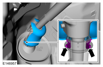
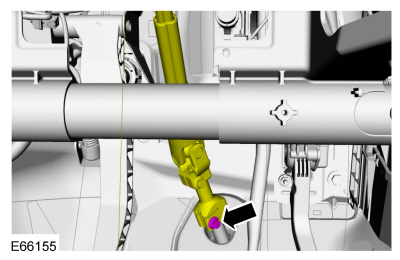
Do not reuse steering column shaft bolts. This may result in fastener failure and steering column shaft detachment or loss
of steering control. Failure to follow this instruction may result in serious injury to vehicle occupant(s).
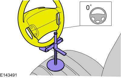
NOTICE: Do not allow the steering column to rotate while the steering column shaft is disconnected or damage to the clockspring may result. If there is evidence that the steering column shaft has rotated, remove and recenter the clockspring. For additional information, refer to Section 501-20B.
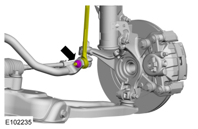
NOTE: The stabilizer bar links are designed with low friction ball joints that have a low breakaway torque.
NOTE: Use the hex-holding feature to prevent the ball stud from turning while removing or installing the stabilizer bar link nut.
On both sides.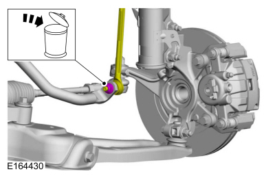
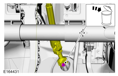
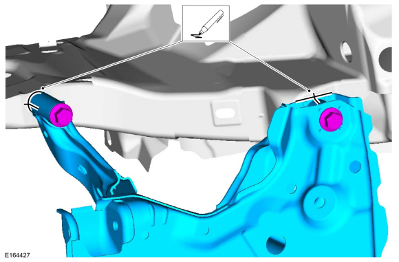
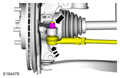
NOTICE: Do not use a hammer to separate the outer tie-rod end from the wheel knuckle or damage to the wheel knuckle may result.
NOTICE: Use care when installing the tie rod separator or damage to the outer tie-rod end boot may occur.
On both sides.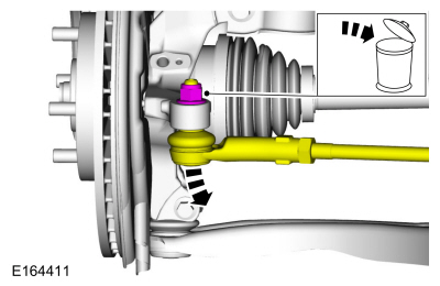
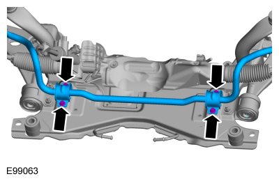
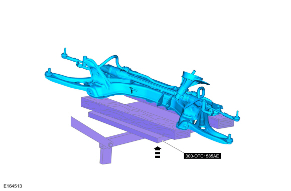
NOTE: 1.6L shown, 1.0L Fox similar.
NOTE: This step is not necessary when installing a new component.
NOTE: Note the position of the component before removal.
Installation
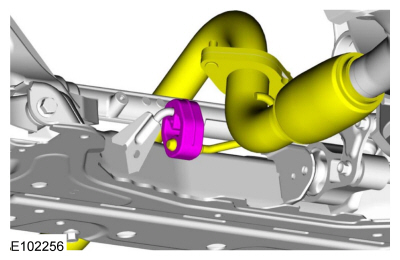
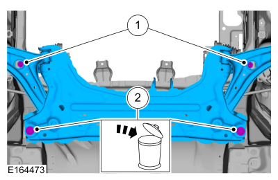
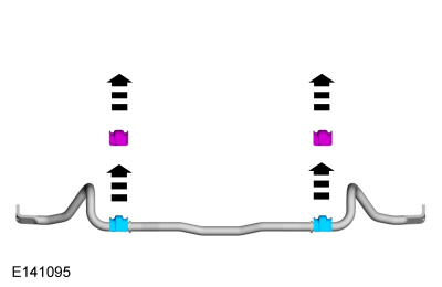
NOTICE: The stabilizer bar bushings must be positioned correctly with the slit in the bushing toward the rear of the vehicle or damage to the bushings may occur.
NOTE: This step is not necessary when installing a new component.
NOTE: Make sure that the mating faces are clean and free of foreign material.
Make sure that these components are installed to the noted removal position.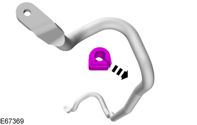
NOTE: This step is not necessary when installing a new component.
NOTE: Make sure that the clamp is installed to the same orientation as when removed.
On both sides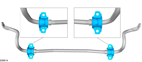
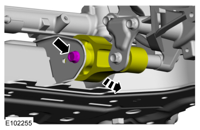
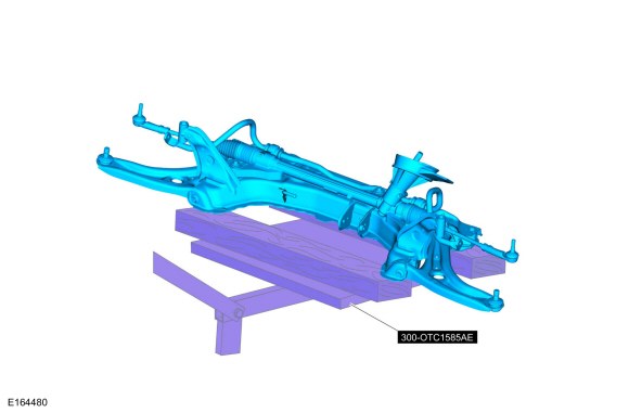
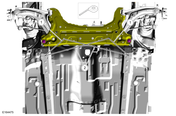
NOTE: If installing the subframe that was previously removed.
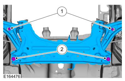
On both sides.
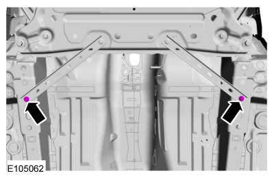
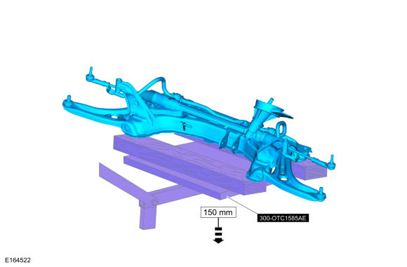
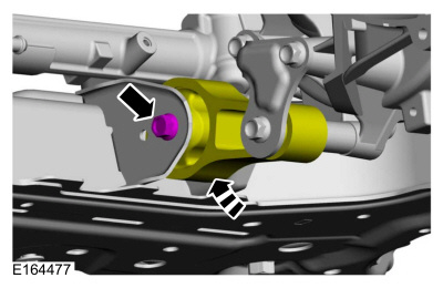
NOTE: If installing a new subframe, measure for correct positioning of the subframe to vehicle underbody.
NOTE: RH and LH dimensions are identical. All measurements on center.
NOTE: 1.6L shown, 1.0L Fox similar.
WARNING:
Do not reuse steering column shaft bolts. This may result in fastener failure and steering column shaft detachment or loss
of steering control. Failure to follow this instruction may result in serious injury to vehicle occupant(s).
Copyright © Ford Motor Company