| 211-02 Power Steering | 2014 Fiesta |
| Description and Operation | Procedure revision date: 04/10/2013 |
System Operation
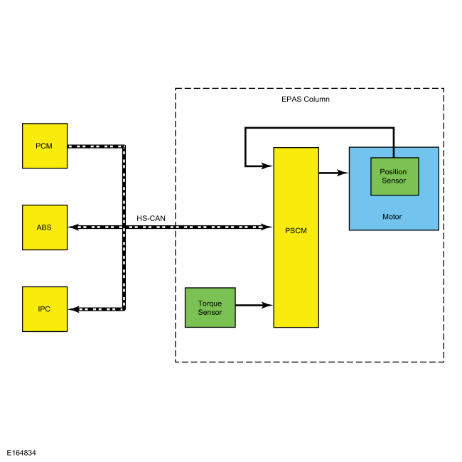
System Diagram
Network Message Chart
Module Network Input Messages: PSCM
| Broadcast Message | Originating Module | Message Purpose |
|---|---|---|
| Engine speed | PCM | Engine speed is monitored to initiate EPAS activation and continued operation. |
| Engine status | PCM | Used to provide the PSCM with the current engine status; off, ready, cranking, running, stalled, afterrum, shutdown or not defined. |
| Vehicle configuration data | IPC | Used to provide the PSCM with the current vehicle configuration. |
| Vehicle configuration / information | IPC | Used to compare the PSCM configuration against the vehicle's specific configuration (central car configuration). |
| Vehicle speed | PCM | Used to determine the necessary level of steering assist. |
| Wheel speed data | ABS | Used to validate the steering wheel component angle by comparing the rotational speeds of each wheel. The difference in the speed of each wheel is used to derive a steering angle for comparison against the absolute steering angle sensor. |
EPAS System
The PSCM controls the functions of the EPAS system and communicates with other modules over the HS-CAN .
To activate, the EPAS system needs to be connected to battery voltage at the hot at all times input and at the ignition/run input to the PSCM . In addition, the system must communicate with other modules over the HS-CAN . The PSCM must receive the engine status signal from the PCM to be set into operation mode.
The main input for calculating the level of steering assist is the steering shaft torque sensor signal. Vehicle speed is also taken into consideration to achieve the vehicle speed dependent steering assist characteristic.
The steering shaft is composed of an input shaft and an output shaft. The two parts of the steering shaft are connected to one another via a torsion bar. When the driver turns the steering wheel, torsion occurs in the steering shaft. The amount of torsion depends on the frictional force between the tires and the road surface. The torsion is increased by the use of the torsion bar, causing relative movement between the input and output shafts. This relative movement is detected by a steering shaft torque sensor and transmitted to the PSCM . The relative movement is the main parameter for calculating the control current for the EPAS motor and thus for the power assisting force. The PSCM uses a reversible motor to apply the steering assist.
The PSCM continually monitors and adjusts steering efforts based on the torque sensor, motor position and HS-CAN inputs to enhance the feel of the steering system. As vehicle speed increases, the amount of assist decreases to improve and enhance road feel at the steering wheel. As vehicle speed decreases, the amount of assist increases to ease vehicle maneuvering. Compensation is made to reduce the effect of pull or drift that can be experienced when driving on roads with a high degree of camber. Also compensation for the impact of wheel imbalance on steering feel is made up to a predetermined threshold.
The steering shaft torque sensor senses the torque at the steering wheel. It is hard wired to the PSCM and works by measuring the relative rotation between an input and output shaft which are connected by a torsion bar. The torque sensor sends out 2 PWM signals which allows a channel to channel cross-check and an accurate correction of the neutral point.
The PSCM is self-monitoring and is capable of setting and storing Diagnostic Trouble Codes (DTCs). Depending on the DTC set, the PSCM may enter a failure mode. In addition, the PSCM may send a request to the IPC to display a message in the message center, alerting the driver of a potential EPAS concern. The warning message is sent over the HS-CAN to the IPC .
Failure Modes
When a DTC is present in the PSCM , the EPAS enters 1 of 2 modes of operation.
The EPAS enters a reduced steering assist mode to protect the internal components of the EPAS system when a concern is detected by the PSCM such as low/high battery voltage or over-temperature concerns that are not considered to be a critical safety concern. This reduced steering assist mode gives the steering a heavier than normal feel.
The EPAS system enters a manual steering mode (no electrical steering assistance is provided) when a concern that is considered to be a critical safety concern is detected. In manual steering mode, the vehicle has mechanical steering operation only, which gives steering operation a heavy feel.
Component Description
EPAS Steering Column
The EPAS steering column is an assembly that consists of a PSCM , a variable speed reversible motor, a steering shaft torque sensor and a reduction gearset, all of which are serviced as an assembly with the steering column.
PSCM
The PSCM is the Electronic Control Unit (ECU) for the EPAS system. The module monitors all sensor inputs and HS-CAN messages that relate to the EPAS system and directly controls the output of the EPAS motor.
Steering Shaft Torque Sensor
The steering torque sensor is mounted in the reduction gearset and is used by the PSCM to determine how much force and in which direction the steering wheel is being turned. This is accomplished using the electromagnetic induction between the sensor stator and the sensor rotor.
EPAS Motor
The electric power steering motor is a brushless type with a stator and three phases connected in star-delta. The rotor is a permanent magnet. The rotor position is detected by a total of 3 Hall-effect sensors and transmitted to the PSCM .
Reduction Gearset
The reduction gearset consists of a worm gear which is permanently attached to the steering shaft and a worm shaft connected to the rotor of the EPAS motor.
Copyright © Ford Motor Company