| 307-05 Automatic Transmission External Controls - Vehicles With: 6-Speed PowerShift Transmission - DPS6/6DCT250
|
2014 Fiesta
|
| Diagnosis and Testing
|
Procedure revision date:
05/17/2013
|
External Controls
Inspection and Verification
-
Verify the customer concern.
-
Visually inspect for obvious signs of mechanical or electrical damage.
|
Mechanical
|
Electrical
|
|
Transmission selector lever cable
|
fuse 18 (10A)
|
|
Manual control lever
|
fuse 22 (7.5A)
|
|
Selector lever
|
switch
|
|
Selector lever knob
|
Brake Shift Interlock Actuator (BSIA)
|
|
|
Wiring harness
|
|
Terminals
|
|
Connectors
|
|
SelectShift™ switch
|
-
If an obvious cause for an observed or reported concern is found, correct the cause (if possible) before proceeding to the
next step.
-
If the cause is not visually evident, verify the symptom and refer to the Symptom Chart.
DTC Chart(s)
DTC Chart -
DTC Chart(s)
DTC Chart -
Symptom Chart(s)
Symptom Chart: External Controls
Diagnostics in this manual assume a certain skill level and knowledge of Ford-specific diagnostic practices.
REFER to:
Diagnostic Methods
(100-00 General Information, Description and Operation).
In most circumstances, the
sets a
to help guide with diagnostics. Refer to the
Chart before using the Symptom Chart. The Symptom column lists the vehicle condition. The Possible Sources column lists a
detailed vehicle condition. The Action column lists the action to be performed to determine the cause of the condition. Each
action lists the components that can cause the condition and the individual components in that system. The components are
listed in order of disassembly. Use the list of components and the required action to focus on disassembly inspections for
the root cause of the concern.
| Symptom
|
Possible Sources
|
Action
|
- Brake shift interlock system does not release/lock correctly
|
- Circuitry shorted to ground
|
|
|
|
|
|
|
|
- Brake Shift Interlock Actuator (BSIA) solenoid
|
- INSTALL a new selector lever assembly.
REFER to:
Selector Lever Assembly
(307-05 Automatic Transmission External Controls - Vehicles With: 6-Speed PowerShift Transmission - DPS6/6DCT250, Removal and Installation).
|
- Selector lever will not shift from PARK
|
|
- VERIFY selector lever cable adjustment.
REFER to:
Selector Lever Cable Adjustment
(307-05 Automatic Transmission External Controls - Vehicles With: 6-Speed PowerShift Transmission - DPS6/6DCT250, General Procedures).
|
|
|
- Selector lever cable retaining clip or bracket
|
- INSTALL a new selector lever cable retaining clip or bracket.
REFER to:
Selector Lever Cable
(307-05 Automatic Transmission External Controls - Vehicles With: 6-Speed PowerShift Transmission - DPS6/6DCT250, Removal and Installation).
|
|
|
- Broken selector lever cable
|
- INSTALL a new selector lever cable.
REFER to:
Selector Lever Cable
(307-05 Automatic Transmission External Controls - Vehicles With: 6-Speed PowerShift Transmission - DPS6/6DCT250, Removal and Installation).
|
- SelectShift™ does not operate correctly
|
- Circuitry open or shorted to ground
|
- CLEAR the
and PERFORM the
self-test. If the Diagnostic Trouble Codes (DTCs) return,
GO to Pinpoint Test B
|
|
|
|
|
- Selector lever linkage is out of correct gear relationship
|
- Selector lever linkage out of adjustment
- Manual control lever not aligned correctly on the sensor (flat surfaces do not line up)
- Loose selector lever cable bracket
|
-
REFER to:
Selector Lever Cable Adjustment
(307-05 Automatic Transmission External Controls - Vehicles With: 6-Speed PowerShift Transmission - DPS6/6DCT250, General Procedures).
|
- Vibration - a high frequency (20-80 Hz) that is felt through the seat or selector lever. Changes with engine speed
|
- Selector lever cable grounded out or loose
|
-
REFER to:
Selector Lever Cable
(307-05 Automatic Transmission External Controls - Vehicles With: 6-Speed PowerShift Transmission - DPS6/6DCT250, Removal and Installation).
|
- The ignition key cannot be returned to the OFF position or the ignition key can be turned to the OFF position when the selector
lever is not in
|
- Wiring, terminals or connectors
- Key removal inhibit solenoid (part of the ignition switch)
- Park detect switch (part of the selector lever)
- Mechanical damage to the selector lever, selector lever cable or selector lever knob
|
|
- The PRNDL indicator does not illuminate
|
- Wiring, terminals or connectors
- Park detect switch (part of the selector lever assembly)
|
|
Pinpoint Tests
Diagnostic Overview
Diagnostics in this manual assume a certain skill level and knowledge of Ford-specific diagnostic practices.
REFER to:
Diagnostic Methods
(100-00 General Information, Description and Operation).
Refer to Wiring Diagrams Cell 37 for schematic and connector information.
Brake Shift Interlock Actuator (BSIA) B2572
Normal Operation and Fault Conditions
The
provides power to the Brake Shift Interlock Actuator (BSIA) solenoid. When the
receives a brake pedal applied input, voltage is applied to the brake shift interlock solenoid. When the solenoid is energized,
the plunger is pulled inward allowing the selector lever to move from the
position.
DTC Fault Trigger Conditions
|
DTC
|
Description
|
Fault Trigger Conditions
|
|
B2572
|
Brake Shift Interlock Output Circuit Failure
|
The associated circuitry connected to the
or fuse, or the
itself may have an issue causing a brake shift interlock concern.
|
Possible Sources
-
Connectors damaged or pushed-out terminals, corrosion, loose wires and missing or damaged seals
-
Brake Shift Interlock Actuator (BSIA) solenoid
-
-
PINPOINT TEST A : BRAKE SHIFT INTERLOCK ACTUATOR (BSIA) B2572
| A1
TEST THE BRAKE LIGHTS
|
-
Apply the brake pedal and view the brake lights.
Do the brake lights illuminate?
| No
|
REFER to:
Stoplamps
(417-01 Exterior Lighting, Diagnosis and Testing).
|
|
| A2
TEST THE TCM (TRANSMISSION CONTROL MODULE)
INTERNAL GROUND CIRCUIT OPERATION
|
-
Using the diagnostic scan tool, monitor the SHFTLCK_ALLW and BOO_TCM PIDS, while pressing the brake pedal off and on.
Does the SHFTLCK_ALLW and BOO_TCM status change?
|
| A3
TEST THE BSIA POWER CIRCUIT
|
-
Disconnect Selector Lever C3245
.
-
Measure.
|
Positive Lead
|
Measurement / Action
|
Negative Lead
|
|
C3245-1
|

|
Ground
|
Is the voltage greater than 10 volts?
|
| A4
TEST THE BSIA GROUND CIRCUIT FOR AN OPEN
|
-
Measure.
|
Positive Lead
|
Measurement / Action
|
Negative Lead
|
|
C3245-12
|

|
C1750A-49
|
Is the resistance less than 5 ohms?
| Yes
|
INSTALL a new selector lever assembly.
REFER to:
Selector Lever Assembly
(307-05 Automatic Transmission External Controls - Vehicles With: 6-Speed PowerShift Transmission - DPS6/6DCT250, Removal and Installation).
|
|
Diagnostic Overview
Diagnostics in this manual assume a certain skill level and knowledge of Ford-specific diagnostic practices.
REFER to:
Diagnostic Methods
(100-00 General Information, Description and Operation).
Refer to Wiring Diagrams Cell 37 for schematic and connector information.
SelectShift™
Normal Operation and Fault Conditions
The SelectShift™ switch is a toggle switch integral to the selector lever knob. When the selector lever is placed in the S
position, the upshift/downshift feature becomes activated. If a new switch is required install a new selector lever knob.
DTC Fault Trigger Conditions
|
DTC
|
Description
|
Fault Trigger Conditions
|
|
P0815
|
Upshift Switch Circuit
|
The
detects a voltage high signal when an upshift is requested.
|
|
P0816
|
Downshift Switch Circuit
|
The
detects a voltage high signal when a downshift is requested.
|
Possible Sources
-
Connectors damaged or pushed-out terminals, corrosion, loose wires and missing or damaged seals
-
SelectShift™ switch
-
PINPOINT TEST B : SELECTSHIFT™
| B1
CHECK THE SELECTSHIFT™ CIRCUITS FOR AN OPEN
|
-
Disconnect Selector LeverC3245
.
-
Inspect for damaged or pushed-out terminals.
-
Measure.
|
Positive Lead
|
Measurement / Action
|
Negative Lead
|
|
C3245-11
|
|
C1750A-52
|
|
C3245-10
|
|
C1750A-10
|
|
C3245-9
|
|
C1750A-9
|
Is the resistance less than 3 ohms?
|
| B2
CHECK THE SELECTSHIFT™ CIRCUITS FOR A SHORT TO GROUND
|
-
Measure.
|
Positive Lead
|
Measurement / Action
|
Negative Lead
|
|
C3245-11
|
|
Ground
|
|
C3245-10
|
|
Ground
|
|
C3245-9
|
|
Ground
|
Is the resistance greater than 10,000 ohms?
|
| B3
CHECK THE SELECTSHIFT™ SWITCH UPSHIFT SIGNAL CIRCUIT FOR AN OPEN
|
-
Connect Selector Lever C3245
.
-
Measure.
|
Positive Lead
|
Measurement / Action
|
Negative Lead
|
|
C1750A-52
|
|
C1750A-9
|
Is the resistance less than 1.5 ohms with upshift selected and greater than 10,000 ohms when released?
|
| B4
CHECK THE SELECTSHIFT™ SWITCH DOWNSHIFT SIGNAL CIRCUIT FOR AN OPEN
|
-
Measure.
|
Positive Lead
|
Measurement / Action
|
Negative Lead
|
|
C1750A-52
|
|
C1750A-10
|
Is the resistance less than 1.5 ohms with downshift selected and greater than 10,000 ohms when released?
| Yes
|
CHECK
for any applicable
. If a
exists for this concern, discontinue this test and follow the
instructions. If no
address this concern, INSTALL a new
.
REFER to:
Transmission Control Module (TCM)
(307-01 Automatic Transmission - Vehicles With: 6-Speed PowerShift Transmission - DPS6/6DCT250, Removal and Installation).
PROGRAM the
with the latest calibration level.
|
|
| B5
CHECK THE UPSHIFT RETURN CIRCUIT AT THE SELECTSHIFT™ SWITCH CONNECTOR
|
-
Disconnect SelectShift™ connector in the selector lever assembly.
-
Inspect for damaged or pushed-out terminals.
-
Measure.
|
Positive Lead
|
Measurement / Action
|
Negative Lead
|
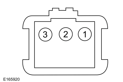 (Female side) Pin 3
|
|
(Female side) Pin 2
|
Is the resistance less than 1.5 ohms with upshift selected and greater than 10,000 ohms when released?
| Yes
|
INSTALL a new selector lever assembly.
REFER to:
Selector Lever Assembly
(307-05 Automatic Transmission External Controls - Vehicles With: 6-Speed PowerShift Transmission - DPS6/6DCT250, Removal and Installation).
|
| No
|
INSTALL a new selector lever knob.
REFER to:
Selector Lever Knob
(307-05 Automatic Transmission External Controls - Vehicles With: 6-Speed PowerShift Transmission - DPS6/6DCT250, Removal and Installation).
|
|
| B6
CHECK THE DOWNSHIFT SIGNAL CIRCUIT AT THE SELECTSHIFT™ SWITCH CONNECTOR
|
-
Disconnect SelectShift™ connector in the selector lever assembly.
-
Inspect for damaged or pushed-out terminals.
-
Measure.
|
Positive Lead
|
Measurement / Action
|
Negative Lead
|
|
(Female side) Pin 1
|
|
(Female side) Pin 2
|
Is the resistance less than 1.5 ohms with downshift selected and greater than 10,000 ohms when released?
| Yes
|
INSTALL a new selector lever assembly.
REFER to:
Selector Lever Assembly
(307-05 Automatic Transmission External Controls - Vehicles With: 6-Speed PowerShift Transmission - DPS6/6DCT250, Removal and Installation).
|
| No
|
INSTALL a new selector lever knob.
REFER to:
Selector Lever Knob
(307-05 Automatic Transmission External Controls - Vehicles With: 6-Speed PowerShift Transmission - DPS6/6DCT250, Removal and Installation).
|
|
Copyright © Ford Motor Company