| 204-04B Tire Pressure Monitoring System (TPMS) | 2014 Fiesta |
| Description and Operation | Procedure revision date: 04/18/2013 |
System Operation
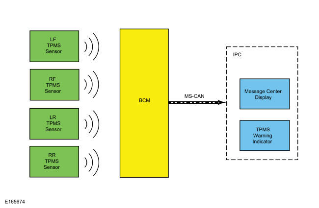
System Diagram
Network Message Chart
TPMS Network Input Messages
| Broadcast Message | Originating Module | Message Purpose |
|---|---|---|
| TPMS data | BCM | Communicates tire pressure information to the IPC . |
TPMS Function
The TPMS monitors tire pressure using 4 valve stem mounted TPMS sensors, these sensors transmit tire pressure data to the BCM . The TPMS sensor locations and unique identifiers are trained (calibrated) to the BCM based on the training order. The BCM compares the tire pressure data sent by the sensors with a programmed desired tire pressure. This programmed pressure is the same pressure indicated on the VC label. If the tire pressure deviates from the programmed tire pressure the BCM , using the MS-CAN , signals the IPC to illuminate the TPMS warning indicator and to display a message in the message center. The programmed desired tire pressure cannot be changed.
For vehicles with different front and rear tire pressures, the tire pressures must be adjusted and the
TPMS
sensors must be trained following a tire rotation.
Refer to:
Tire Pressure Monitoring System (TPMS) Sensor Location Calibration
(204-04B Tire Pressure Monitoring System (TPMS), General Procedures).
Failure to train the sensors results in a false low tire pressure event which causes the
TPMS
warning indicator to illuminate.
For vehicles with the same front and rear tire pressures, tire rotation does not affect the TPMS .
The diagnostic scan tool is a useful tool in diagnosing TPMS concerns and may be used to verify the accuracy of the tire pressure data transmitted by the TPMS sensors. This is accomplished by comparing the BCM tire pressure PID data to the actual tire pressure using a digital tire pressure gauge.
Wheel Rotation and Sensor Training Techniques
Training known good sensors from another vehicle cannot differentiate between a faulted module and Radio Frequency Interference
(RFI), as some noise source could be preventing the module from receiving the tire pressure status from the original sensors
as well as the known good sensors. This technique can be used to differentiate between a sensor and a module concern. If the
module in the suspect vehicle cannot train any of the sensors on the vehicle and, likewise, cannot train known good sensors
from another vehicle, then the concern is with the module or Radio Frequency Interference (RFI) and not with the original
sensors. The original sensors should not be replaced. If a sensor in a certain location has caused several events, yet the
sensor trains and seems to operate normally, moving that particular wheel to a different location on the vehicle is a good
way to isolate the concern to a certain sensor/wheel location. Rotate the wheels and road test the vehicle. This can be
done in an attempt to replicate the concern and help determine if the concern followed the sensor or remained in the original
sensor location. If the vehicle has been stationary for more than 15 minutes, the sensors go into a sleep mode to conserve
battery power and they will need to be woken up so they transmit the latest tire pressure information to the
BCM
.
Refer to:
Tire Pressure Monitoring System (TPMS) Sensor Activation
(204-04B Tire Pressure Monitoring System (TPMS), General Procedures).
Training Sensors in a Different Order
If the first sensor fails the TPMS training procedure, the BCM aborts the entire procedure. Starting the training procedure at a different wheel is a technique that can be used to determine if the remaining sensors can train to the module. This can help save time determining if one sensor is damaged, other sensors are having concerns or the BCM is experiencing training difficulties with a certain TPMS sensor location.
TPMS Warning Indicator
The TPMS warning indicator and vehicle message center occasionally displays faults that cannot be resolved by the customer. Treat these messages as TPMS faults that must be serviced.
TPMS Warning Indicator Illuminates Continuously
The TPMS warning indicator remains on continuously and the message center displays LOW TIRE PRESSURE when any of the tire pressures fall below the low pressure limit. When this condition exists, adjust the tire pressure to the recommended cold tire pressure indicated on the VC label.
Tire Pressure Monitoring System (TPMS) Warning Indicator Flashes
The TPMS warning indicator flashes for 75 seconds and then remains on continuously when the ignition is set to ON and the TPMS is malfunctioning. The PID TP_STAT can be used to determine why the TPMS warning indicator is flashing.
TPMS PID Definitions
The BCM monitors the TPMS status. The current status can be viewed by accessing the TPMS status PID : TPMS_STAT using the scan tool. This helps identify the current system status and may aid in diagnosing the system. The PID has 4 valid states:
Last Warning Event PID Definitions
The TPMS uses the TPMS last warning event Parameter Identifications (PIDs) to store detailed information about the last 5 times the TPMS warning indicator was activated. These Parameter Identifications (PIDs) can be used to acquire more information about a particular TPMS event, but must be used carefully.
| PIDs | Definition |
|---|---|
| EVT1_AGE_IGN through EVT5_AGE_IGN | The number of key cycles since the TPMS was activated. This PID cycles from zero to 255 and then starts over from zero again. This can be used to determine how long ago a TPMS event occurred and the time (in key cycles) between events. |
| EVT1_TR_LOC through EVT5_TR_LOC | This is the last programmed location for the TPMS sensor identifier causing each TPMS event. Due to tire rotation, the sensor may no longer be at the original location. It is suggested that all the Parameter Identifications (PIDs) be recorded, the system retrained, and then the sensor identifier Parameter Identifications (PIDs) be used to pinpoint the actual location of each sensor. |
| EVT1_PSI through EVT5_PSI | This is the tire pressure associated with each TPMS indicator event. This can be used along with the function code to clearly identify the TPMS events that were strictly due to low pressure. It can also be used to determine when a sensor is transmitting inaccurate tire pressure. |
| EVT1_SNSR_ST through EVT5_SNSR_ST |
|
| EVT1_SNSR_ID through EVT5_SNSR_ID | This is the identifier of the sensor involved in each TPMS event. EVT1 is the most recent event that triggered the TPMS warning indicator. |
Radio Frequency Interference
Radio Frequency Interference (RFI) can be caused by:
Original Equipment Manufacturer (OEM) Modules
In some cases the Radio Frequency Interference (RFI) may actually be caused by a module or ground on the vehicle. Depending on the severity of the concern, a dirty ground, improperly built ground shield or module can disable the system. Modules that have microcontrollers using clock circuits to create timing pulses for the microprocessor may radiate Radio Frequency Interference (RFI).
Using Customer Electronics to Pinpoint Radio Frequency Interference
This method can be a way to determine the cause of a concern well before the sensors and module are replaced with little or no effect on system performance. Since this takes more up front work, it relies on working with the customer to determine what equipment was being used at the time of the event. Question the customer about what kind of devices they are using. Determine which power points are being used and, if necessary, ask that the devices be activated to determine their affect on the TPMS .
Options for Eliminating Intermittent TPMS Operation Caused by Radio Frequency Interference (RFI)
In summary, if the Radio Frequency Interference (RFI) source is present and cannot be moved or replaced, the intermittent concern remains. The TPMS must accept the unwanted system operation the Radio Frequency Interference (RFI) can cause.
Ambient Temperature Change and Tire Pressure
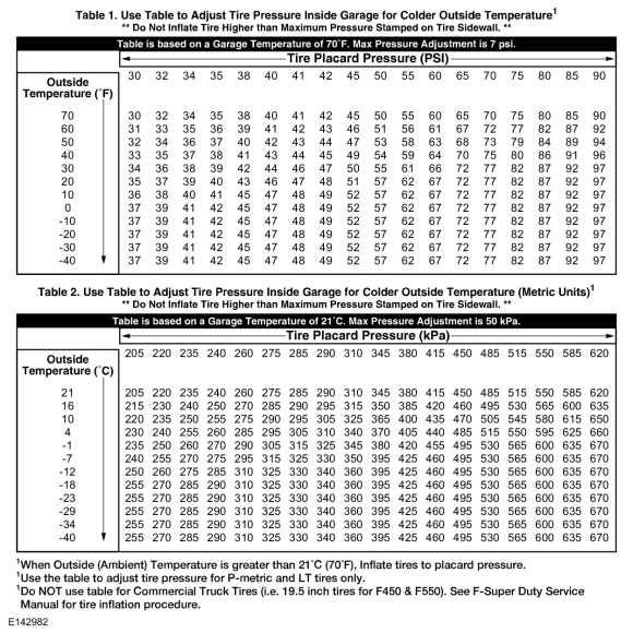
Tire pressures fluctuate with temperature changes. For this reason, tire pressures must be set to specification when tires are at outdoor ambient temperatures. If the vehicle is allowed to warm up to shop temperatures, and the outside temperature is less than shop temperature, the tire inflation pressure must be adjusted accordingly.
If the tires are inflated to specification at shop temperatures, and the vehicle is moved outdoors when the outdoor ambient temperature is significantly lower, the tire pressure may lower enough to be detected by the TPMS sensor and activate the TPMS warning indicator.
As the ambient temperature decreases by -12.2° C (10° F), tire pressure decreases 6.9 kPa (1 psi). Adjust the tire pressure by 6.9 kPa (1 psi) for each -12.2° C (10° F) of ambient temperature drop as necessary to keep the tire at the specified VC label pressure. To adjust the tire pressure indoors for colder outside temperatures, refer to the following table.
Component Description
BCM
The BCM is a multifunction module that monitors all sensor inputs and all CAN messages that relate to the TPMS . The BCM records and retains the unique sensor identifier of each TPMS sensor.
The
BCM
retains the previous sensor location information following a tire rotation, for the
BCM
to learn the new sensor location, the sensors must be trained (calibrated) to the
BCM
. Additionally, the sensors must be trained when a new
BCM
is installed.
Refer to:
Tire Pressure Monitoring System (TPMS) Sensor Location Calibration
(204-04B Tire Pressure Monitoring System (TPMS), General Procedures).
When installing a new
BCM
, there are several procedures that must be carried out for the module to function correctly. These procedures include, but
are not limited to;
PMI
, anti-theft parameter reset, programming keyless entry remote and setting customer preferences.
Refer to:
Body Control Module (BCM)
(419-10 Multifunction Electronic Modules, Removal and Installation).
TPMS Sensor
Each of the 4 TPMS tire pressure sensors contain a battery, a tire pressure sensor and a radio transmitter. The TPMS sensor radio transmissions are sent approximately once every 60 seconds when the vehicle speed exceeds 32.2 km/h (20 mph) and once every 6 hours when the sensors are in sleep mode.
Copyright © Ford Motor Company