| 206-09 Anti-Lock Brake System (ABS) and Stability Control | 2014 Fiesta |
| Description and Operation | Procedure revision date: 04/18/2013 |
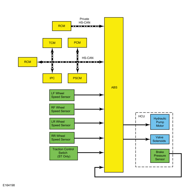
System Operation
System Diagram
Network Message Chart
Module Network Input Messages - ABS Module
| Broadcast Message | Originating Module | Message Purpose |
|---|---|---|
| Accelerator pedal position | PCM | The ABS module uses accelerator pedal position information for correct operation of the traction control, Electronic Stability Control (ESC) and hill start assist functions. |
| Axle ratio - front | PCM | The ABS module uses the front axle ratio information for correct operation of all the stability control functions as well as anti-lock braking. |
| Brake pedal pressed | PCM | This message informs the ABS module the driver has pressed the brake pedal. This message is also used by the ABS module to check the brake pressure sensor located inside the HCU . |
| Door ajar status | IPC | This message is sent to the IPC from the DDM and then to the ABS module. This message informs the ABS module of the current door ajar status. There is a separate message for each door and the liftgate. The ABS module resets the parameters used for the Electronic Stability Control (ESC) function when a door or the liftgate is opened. |
| Engine Revolutions Per Minute (RPM) | PCM | Used to inform the ABS module of the current engine Revolutions Per Minute (RPM). The ABS module uses this information for traction control and Electronic Stability Control (ESC) functions. |
| Engine torque value | PCM | This message provides the ABS module with the current amount of torque being produced by the engine. The ABS module uses this information for correct operation of the traction control, Electronic Stability Control (ESC) and hill start assist functions. |
| Engine status | PCM | This message informs the ABS module of the current status of the engine system; off, ready, cranking, running, stalled, afterrun, shutdown or not defined. |
| Hill start assist setting | IPC | This message informs the ABS module of the current driver selected mode for the hill start assist system; off or automatic. |
| Ignition status | IPC | This message informs the ABS module of the current ignition status; off, accessory, run, start, unknown or invalid. |
| Parking brake status | IPC | This message provides the ABS module with the current parking brake switch status; applied or released. |
| Powertrain torque value | PCM | This message provides the ABS module with the current amount of propelling torque being applied to the driven wheels. The ABS module uses this information for correct operation of the traction control, Electronic Stability Control (ESC) and hill start assist functions. |
| RCM serial number | RCM | The ABS module stores the RCM serial number and verifies the serial number when the vehicle is started or the ignition is set to RUN or ACC. Over time, the ABS module learns the offset of the sensors inside the RCM . When a new serial number is found and the IVD Initialization procedure is carried out using a diagnostic scan tool, the ABS module resets the offset number learned for the Electronic Stability Control (ESC) function. |
| Stability-traction control mode request | IPC | This message informs the ABS module of the current driver selected mode for the traction control system; on or off. |
| Steering angle | PSCM | The ABS module uses steering angle sensor information for Electronic Stability Control (ESC) operation. This message provides the ABS with the current steering wheel angle in degrees. |
| Steering angle status | PSCM | The ABS module uses steering angle sensor information for Electronic Stability Control (ESC) operation. This message provides the ABS with the current steering angle sensor status; okay or not okay. |
| Steering sensor calibration | PSCM | The ABS module uses steering angle sensor information for Electronic Stability Control (ESC) operation. This message provides the ABS with the current steering sensor calibration status; yes (calibrated) or no (not calibrated). |
| Tire size data | PCM | The ABS module uses tire size data for correct operation of all the stability control functions as well as anti-lock braking. |
| Transmission gear position | PCM | This message informs the ABS module of which gear the transmission is currently using, this is used for the hill start assist system and the Electronic Stability Control (ESC) functions. The Electronic Stability Control (ESC) function does not operate when the transmission is in REVERSE. |
| Transmission gear lever position | TCM | This message informs the ABS module of the driver selected transmission gear position, this is used for the hill start assist system and the Electronic Stability Control (ESC) functions. The Electronic Stability Control (ESC) function does not operate when the transmission is in REVERSE. |
| Transmission shift in progress | TCM | This message informs the ABS module that the transmission is currently upshifting or downshifting. The ABS module uses this information for correct operation of the traction control and Electronic Stability Control (ESC) functions. |
| Vehicle configuration data | IPC | This message provides the ABS module with the current optional and configured features such as transaxle type, keyless entry and VIN . |
Anti-Lock Brake System (ABS) Function
The ABS module continuously monitors brake pedal input, lateral vehicle motion and the rotational speed of each wheel. The PCM sends the brake pedal switch information to the ABS module over the HS-CAN , while the RCM sends lateral acceleration sensor information to the ABS module over a private HS-CAN . Wheel speed information is retrieved by the ABS module using 4 wheel speed sensors. When the ABS module detects an impending wheel lock during a braking event, the ABS module regulates brake pressure to the appropriate brake calipers or wheel cylinders by opening and closing the appropriate solenoid valves inside the HCU while the hydraulic pump motor is activated. Once the affected wheel returns to the desired speed, the ABS module returns the solenoid valves in the HCU to their normal position.
The ABS module has 2 self-test options, one uses a diagnostic scan tool and the other is carried out when the ABS module is initialized (ignition ON). During either self-test, the ABS module carries out a preliminary electrical check of the system sensors and activates the hydraulic pump motor for approximately one-half second. During this time, a buzzing or humming noise may be heard and a vibration may be felt in the brake pedal and is a normal condition. During the module initialized self-test, the pump motor check is carried out at approximately 10 km/h (6.2 mph). Any malfunction detected in the system causes the ABS module to set a DTC , disable the ABS function and send a message over the HS-CAN to the IPC to illuminate the ABS warning indicator. When the ABS module disables the ABS function, the base hydraulic power assisted braking system remains functional unless the red brake warning indicator is also illuminated.
Electronic Brake Force Distribution (EBD)
On initial application of the brake pedal, full pressure is applied to the rear brakes. The ABS module uses wheel speed sensor inputs to evaluate rear wheel slip. Once the rear wheel slip exceeds a predetermined threshold, the ABS module commands the HCU to close the appropriate isolation valves to hold the rear brake pressure constant while allowing the front brake pressure to build. This creates a balanced braking condition between the front and rear wheels. If the rear wheel slip continues and exceeds a second predetermined threshold, the ABS module commands the HCU to open the dump valves to decrease the rear brake pressure and allow the rear wheels to recover. A slight bump may be felt in the brake pedal when EBD is active.
If the ABS function is disabled due to a DTC being present in the ABS module, EBD continues to function unless the DTC is for wheel speed sensors or the HCU . When EBD is disabled, the ABS warning indicator, the red brake warning indicator and stability-traction control OFF indicator (sliding car OFF icon) illuminate.
AdvanceTrac®
The AdvanceTrac® system includes the traction control function and the Electronic Stability Control (ESC) function. Both systems work independently and together to stabilize the vehicle.
On vehicles equipped with a 1.6L Gas Turbo Direct Injection (GTDI) engine, AdvanceTrac® provides 3 modes of operation; normal, sport and off. In normal mode both traction control and Electronic Stability Control (ESC) are active with normal thresholds for wheel spin and vehicle slip. In sport mode both traction control and Electronic Stability Control (ESC) are active but the thresholds for wheel spin and vehicle slip are raised to allow more wheel spin and vehicle slip before the system engages. In off mode, both traction control and Electronic Stability Control (ESC) are completely disengaged. The stability-traction control switch is used to change between the 3 modes. The AdvanceTrac® system defaults to normal mode when the ignition is cycled from OFF to ON. Pressing the switch once activates sport mode, pressing and holding the switch pressed for 5 seconds shuts the AdvanceTrac® system off and pressing the switch once when in sport or off mode activates normal mode.
When sport mode is activated the stability-traction control OFF indicator (sliding car OFF icon) in the IPC illuminates and the message center displays SPORT MODE. When AdvanceTrac® system is switched off, the stability-traction control OFF indicator (sliding car OFF icon) in the IPC illuminates and the message center displays ESC OFF. When normal mode is activated, the stability-traction control OFF indicator (sliding car OFF icon) in the IPC is extinguished and the message center does not display anything.
Traction Control
The ABS module continuously monitors and compares the rotational speed of the drive wheels in relation to the non-driven wheels. When the drive wheels begin to spin faster than the non-driven wheels, the ABS module regulates brake pressure to the appropriate brake calipers or wheel cylinders by opening and closing the appropriate solenoid valves inside the HCU while the hydraulic pump motor is activated. At the same time, the ABS module calculates how much engine torque reduction is required to eliminate the wheel slip and sends this information to the PCM over the HS-CAN . The ABS module also sends a traction event message to the IPC over the HS-CAN . When the PCM receives the torque reduction message, it adjusts engine timing and decreases fuel injector pulses to reduce the engine torque to the requested level. When the IPC receives the traction event message, it flashes the stability-traction control indicator (sliding car icon). Once the driven wheel speed returns to the desired speed, the ABS module returns the solenoid valves in the HCU to their normal position, deactivates the hydraulic pump motor and stops sending the traction event and torque reduction messages. The PCM returns engine timing and fuel injectors to normal operation and the IPC extinguishes the stability-traction control indicator (sliding car icon). After the vehicle speed exceeds 100 km/h (62.1 mph), traction control is accomplished only through the PCM torque control.
On vehicles equipped with a 1.6L Gas Turbo Direct Injection (GTDI) engine, traction control is disabled using the stability-traction control switch which is wired directly to the ABS module. When the driver disables traction control through the switch, the ABS module sends a traction control status message to the IPC over the HS-CAN . The ABS module takes no further action in regards to traction control until the driver activates the function or until the ignition is cycled from OFF to ON.
On all other vehicles, traction control is disabled using the message center, refer to the Owner's Literature for instructions on disabling traction control. When the driver disables traction control through the message center, the IPC communicates traction control status to the ABS module over the HS-CAN . The ABS module takes no further action in regards to traction control until the driver activates the function or until the ignition is cycled from OFF to ON.
Traction control is disabled if there is a wheel speed sensor or solenoid valve DTC present in the ABS module. Traction control is also disabled if there is a communication error between the ABS module and the PCM . When traction control is disabled, either by driver input or the presence of a DTC , the IPC illuminates the stability-traction control OFF indicator (sliding car OFF icon) and displays ESC OFF in the message center.
Electronic Stability Control (ESC)
The ABS module continuously monitors the vehicle motion relative to the intended course. This is done by using sensors to compare the steering wheel input and the yaw rate sensor input with the actual vehicle motion.
The PSCM sends the steering wheel angle and rate of change information to the ABS module over the HS-CAN while the RCM sends yaw rate sensor information to the ABS module over a private HS-CAN . If the ABS module determines from the inputs the vehicle is unable to travel in the intended direction, it regulates the brake pressure to the appropriate brake calipers or wheel cylinders by opening and closing the appropriate solenoid valves inside the HCU while the hydraulic pump motor is activated.
At the same time the ABS module calculates how much engine torque reduction is required to reduce vehicle speed to help stabilize the vehicle and sends this information to the PCM over the HS-CAN . The ABS module also sends a stability event message to the IPC over the HS-CAN . When the PCM receives the torque reduction message, it adjusts engine timing and decreases fuel injector pulses to reduce the engine torque to the requested level. When the IPC receives the stability event message, it flashes the stability-traction control indicator (sliding car icon). Once the vehicle instability has been corrected, the ABS module returns the solenoid valves in the HCU to their normal position, deactivates the hydraulic pump motor and stops sending the traction event and torque reduction messages. The PCM returns engine timing and fuel injectors to normal operation and the IPC extinguishes the stability-traction control indicator (sliding car icon).
On vehicles equipped with a 1.6L Gas Turbo Direct Injection (GTDI) engine, Electronic Stability Control (ESC) is disabled using the stability-traction control switch which is wired directly to the ABS module. When the driver disables Electronic Stability Control (ESC) through the switch, the ABS module sends an Electronic Stability Control (ESC) status message to the IPC over the HS-CAN . The ABS module takes no further action in regards to Electronic Stability Control (ESC) until the driver activates the function or until the ignition is cycled from OFF to ON.
On all other vehicles, the Electronic Stability Control (ESC) function cannot be disabled by the driver.
Electronic Stability Control (ESC) does not operate with the transmission in REVERSE. Electronic Stability Control (ESC) is disabled if there is a wheel speed sensor, stability sensor or steering angle sensor DTC present in the ABS module. Electronic Stability Control (ESC) is also disabled if there is a communication error between the ABS module and the PSCM or the RCM . When Electronic Stability Control (ESC) is disabled, either by driver input or the presence of a DTC , the ABS module sends an Electronic Stability Control (ESC) status message to the IPC over the HS-CAN . The IPC illuminates the stability-traction control OFF indicator (sliding car OFF icon) and displays ESC OFF in the message center.
Hill Start Assist
When the vehicle is stopped on an incline greater than 1.5 degrees (approximately a 3% grade), the ABS module holds the brake pressure for approximately 1.5 seconds while the driver transitions from the brake pedal to the accelerator pedal. This is accomplished by monitoring several HS-CAN messages and several sensors to determine if the vehicle is stopped and not parked, and if the vehicle is on an appropriate incline. The brake pedal message sent from the PCM over the HS-CAN and the wheel speed sensor inputs allow the ABS module to determine the vehicle has come to a complete stop. The transmission selector lever message sent by the TCM informs the ABS module the vehicle is not parked. The stability sensor messages sent by the RCM over the private HS-CAN enable the ABS module to determine the vehicle is on an incline greater than 1.5 degrees (approximately a 3% grade). Once the above conditions have been met, the hill start assist function automatically engages. As the driver releases the brake pedal, the ABS module commands the HCU to close the isolation valves which maintain the current brake system pressure, preventing the vehicle from rolling down the incline. Once the driver presses the accelerator pedal and the engine Revolutions Per Minute (RPM) increases, the ABS module gradually releases the brake pressure to make sure the vehicle is neither rolling back nor driving off until there is sufficient driving torque to accelerate the vehicle forward (or backward if reversing up the incline).
MyKey® Interaction
Through the MyKey® feature, the traction control function of the stability control system can be configured to be always on or to allow the driver to select the traction control function on or off. The IPC sends a MyKey® status message to the ABS module over the HS-CAN .
On vehicles equipped with a 1.6L Gas Turbo Direct Injection (GTDI) engine, when the traction control function is configured to be always on and a MyKey® restricted key is in use, the ABS module ignores any requests made by the driver to disable the traction control and Electronic Stability Control (ESC) functions.
On all other vehicles, when the traction control function is configured to be always on and a MyKey® restricted key is in use, the IPC ignores any requests made by the driver to disable the traction control function and does not send any traction control disable messages to the ABS module. Refer to the Owner's Literature for additional information on the MyKey® feature and settings.
Stability-Traction Control Indicator (Sliding Car Icon)
Refer to:
Instrument Panel Cluster (IPC) - System Operation and Component Description
(413-01 Instrumentation, Message Center and Warning Chimes, Description and Operation).
Stability-Traction Control Disabled Indicator (Sliding Car OFF Icon)
Refer to:
Instrument Panel Cluster (IPC) - System Operation and Component Description
(413-01 Instrumentation, Message Center and Warning Chimes, Description and Operation).
Component Description
Anti-Lock Brake System (ABS) Module
The ABS module is attached directly to the HCU and is the electronic control unit for all of the ABS and stability control systems. The ABS module monitors all sensor inputs and all HS-CAN messages that relate to ABS and stability control, then directly controls the solenoid valves and the hydraulic pump motor in the HCU .
The
ABS
module and
HCU
are serviced as an assembly. When a new
ABS
and
HCU
assembly is installed, they must be programmed with the vehicle configuration information.
Refer to:
Module Configuration - System Operation and Component Description
(418-01 Module Configuration, Description and Operation).
When an ABS or stability control system fault has been corrected or a new component has been installed, the ABS module must be calibrated. The calibration procedure is required for the stability control sensors to learn the zero-position of the vehicle which means the vehicle must be on a level surface and not moving. The calibration routine is carried out using a diagnostic scan tool.
Hydraulic Control Unit (HCU)
The HCU contains the solenoid valves, the hydraulic pump motor and the pressure sensor used by the ABS for the various stability control systems. The ABS module and the HCU are attached together and are serviced as an assembly.
Wheel Speed Sensor
The wheel speed sensors are active (magneto resistive) sensors that operate on the Hall-effect principle to generate a square wave signal that is proportional to the rotational speed of the wheel. Because these are active sensors, receiving voltage from the ABS module and then sending a varying voltage back to the ABS module, they are able to detect much lower rotational speeds than passive (magnetic inductive) sensors. Each wheel speed sensor is connected to the ABS module by 2 circuits. One circuit provides voltage for sensor operation and the other circuit provides sensor input to the ABS module.
Wheel Speed Sensor Encoders
The wheel speed sensor encoders are several magnets arranged in a circle around one side of the wheel bearing in alternating poles. As the bearing rotates the wheel speed sensor is exposed to alternating north-south magnetic fields. The encoder is part of the wheel bearing and is serviced with the bearing.
Stability Control Sensors
The stability control sensors for the vehicle dynamic system consist of the yaw rate sensor, lateral accelerometer and longitudinal accelerometer. The sensors are housed in the RCM which sends sensor information to the ABS module over a private HS-CAN . If any of the sensors are defective, a new RCM must be installed.
Lateral acceleration has 2 forms. The first is the centrifugal acceleration that is generated when the vehicle travels around in a circle. The second is the acceleration due to gravity. On level ground there is no lateral acceleration due to gravity. However, if the vehicle is parked sideways on a bank or incline, the sensor measures some lateral acceleration due to gravity, even though the vehicle is not moving.
Steering Wheel Rotation Sensor
The steering wheel rotation sensor is an internal component of the EPAS column and is serviced with the column. The steering wheel rotation speed, angle and direction of travel is calculated by the PSCM and sent to the ABS module over the HS-CAN .
Traction Control Switch
The traction control switch is a momentary contact, push button switch that is hardwired to the ABS module. The switch is part of the heated driver seat switch pack and is serviced as an assembly.
Copyright © Ford Motor Company