| 501-11 Glass, Frames and Mechanisms
|
2014 Fiesta
|
| Diagnosis and Testing
|
Procedure revision date:
05/7/2013
|
Glass, Frames and Mechanisms - Vehicles With: One-Touch Up and Down Driver Window
DTC Chart: Body Control Module (BCM)
Diagnostics in this manual assume a certain skill level and knowledge of Ford-specific diagnostic practices.
REFER to:
Diagnostic Methods
(100-00 General Information, Description and Operation).
Body Control Module (BCM) DTC Chart
Symptom Chart(s)
Symptom Chart: Glass, Frames and Mechanisms
Diagnostics in this manual assume a certain skill level and knowledge of Ford-specific diagnostic practices.
REFER to:
Diagnostic Methods
(100-00 General Information, Description and Operation).
Symptom Chart
|
Condition
|
Possible Sources
|
Actions
|
|
All power windows are inoperative
|
-
Refer to the Pinpoint Test
|
GO to Pinpoint Test A
|
|
The passenger front,
rear and
rear power windows are inoperative
|
-
Refer to the Pinpoint Test
|
GO to Pinpoint Test B
|
|
Both front power windows are inoperative
|
-
Refer to the Pinpoint Test
|
GO to Pinpoint Test C
|
|
Both rear power windows are inoperative
|
-
Refer to the Pinpoint Test
|
GO to Pinpoint Test D
|
|
A single power window is inoperative - driver front
|
-
Refer to the Pinpoint Test
|
GO to Pinpoint Test E
|
|
A single power window is inoperative - passenger front
|
-
Refer to the Pinpoint Test
|
GO to Pinpoint Test F
|
|
A single power window is inoperative -
Rear
|
-
Refer to the Pinpoint Test
|
GO to Pinpoint Test G
|
|
A single power window is inoperative -
rear
|
-
Refer to the Pinpoint Test
|
GO to Pinpoint Test H
|
|
The one-touch up/down feature is inoperative
|
-
Refer to the Pinpoint Test
|
GO to Pinpoint Test I
|
|
The defrost system is inoperative -
|
-
Refer to the Pinpoint Test
|
GO to Pinpoint Test A J
|
|
The defrost system is inoperative -
|
-
Refer to the Pinpoint Test
|
GO to Pinpoint Test D M
|
|
The defrost system will not shut off automatically -
|
-
Refer to the Pinpoint Test
|
GO to Pinpoint Test B K
|
|
The defrost system will not shut off automatically -
|
-
Refer to the Pinpoint Test
|
GO to Pinpoint Test E N
|
|
The defrost system
does not illuminate when the defrost system is active -
|
-
Refer to the Pinpoint Test
|
NOTE:
The rear defrost self actuates when the ambient air temperature is less than 5° C (41° F) and engine coolant temperature is
less than 60° C (140° F). The rear window defroster
indicator does not illuminate when the rear defroster self actuates.
GO to Pinpoint Test C L
|
|
The defrost system
does not illuminate when the defrost system is active -
|
|
NOTE:
The rear defrost self actuates when the ambient air temperature is less than 5° C (41° F) and engine coolant temperature is
less than 60° C (140° F). The rear window defroster
indicator does not illuminate when the rear defroster self actuates.
INSTALL a new
module.
REFER to:
Heating, Ventilation and Air Conditioning (HVAC) Control Module
(412-00 Climate Control System - General Information, Removal and Installation).
|
Pinpoint Test(s)
All power windows are inoperative
Refer to Wiring Diagrams Cell 100 for schematic and connector information.
Normal Operation and Fault Conditions
The accessory relay (located in the
) provides all voltage necessary to operate the power windows. The accessory relay is controlled by the
. The master window control switch supplies ground for all window motor operation.
DTC Fault Trigger Conditions
|
DTC
|
Description
|
Fault Trigger Conditions
|
|
B131A:12
|
Delayed Accessory Power: Circuit Short To Battery
|
This
sets when the
detects the accessory relay control circuit is shorted to voltage.
|
Possible Causes
-
Fuse(s)
-
Accessory relay
-
Wiring, terminals or connectors
-
Window control switch
Visual Inspection and Diagnostic Pre-checks
-
Verify that
fuse 12 (60A) and
fuse 7 (7.5A) are OK.
The passenger front,
rear and
rear power windows are inoperative
Refer to Wiring Diagrams Cell 100 for schematic and connector information.
Normal Operation and Fault Conditions
There are two high current voltage circuits to the master window control switch. One of these circuits provides voltage for
front window operation, the other provides voltage for rear window operation. The master window control switch supplies ground
for all window motor operation through two different circuits. One of the circuits provides ground only to the driver front
window, the other provides ground for the passenger front,
rear and
rear window motor operation.
Possible Causes
-
Wiring, terminals or connectors
-
Window control switch
PINPOINT TEST B : THE PASSENGER FRONT, LH (LEFT-HAND)
REAR AND RH (RIGHT-HAND)
REAR POWER WINDOWS ARE INOPERATIVE
| B1
CHECK ALL WINDOW OPERATION FROM THE MASTER WINDOW CONTROL SWITCH
|
|
NOTE:
Make sure the window lock-out switch is in the UNLOCK position.
-
Attempt to operate each window from the master window control switch.
Does the passenger front,
rear or
rear window operate from the master window control switch?
| Yes
|
GO to the Symptom Chart to diagnose the inoperative window(s).
|
|
| B2
CHECK THE MASTER WINDOW CONTROL SWITCH GROUND CIRCUIT FOR AN OPEN
|
-
Disconnect: Master Window Control Switch C504C.
-
Measure:
|
Positive Lead
|
Measurement / Action
|
Negative Lead
|
|
C504C-4
|

|
Ground
|
Is the resistance less than 3 ohms?
|
Both front power windows are inoperative
Refer to Wiring Diagrams Cell 100 for schematic and connector information.
Normal Operation and Fault Conditions
There are two high current voltage circuits to the master window control switch. One of these circuits provides voltage for
front window operation, the other provides voltage for rear window operation. The master window control switch supplies ground
for all window motor operation through two different circuits. One of the circuits provides ground only to the driver front
window, the other provides ground for the passenger front,
rear and
rear window motor operation.
Possible Sources
-
Fuse
-
Wiring, terminals or connectors
-
Window control switch
Visual Inspection and Diagnostic Pre-checks
-
Verify
fuse 34 (30A) is OK.
PINPOINT TEST C : BOTH FRONT POWER WINDOWS ARE INOPERATIVE
| C1
CHECK FOR VOLTAGE TO THE MASTER WINDOW CONTROL SWITCH
|
-
Disconnect: Master Window Control Switch C504A.
-
Measure:
|
Positive Lead
|
Measurement / Action
|
Negative Lead
|
|
C504A-7
|

|
Ground
|
Is the voltage greater than 11 volts?
|
Both Rear Power Windows are Inoperative
Refer to Wiring Diagrams Cell 100 for schematic and connector information.
Normal Operation and Fault Conditions
There are two high current voltage circuits to the master window control switch. One of these circuits provides voltage for
front window operation, the other provides voltage for rear window operation when the master window lock-out switch is in
the UNLOCK position. The master window control switch supplies ground for all window motor operation through two different
circuits. One of the circuits provides ground only to the driver front window, the other provides ground for the passenger
front,
rear and
rear window motor operation.
Possible Sources
-
Fuse
-
Wiring, terminals or connectors
-
Window control switch
Visual Inspection and Diagnostic Pre-checks
-
Verify the lock-out switch is in the UNLOCK position.
-
Verify
fuse 31 (30A) is OK.
PINPOINT TEST D : BOTH REAR POWER WINDOWS ARE INOPERATIVE
| D1
CHECK FOR VOLTAGE TO THE MASTER WINDOW CONTROL SWITCH
|
-
Disconnect: Master Window Control Switch C504C.
-
Measure:
|
Positive Lead
|
Measurement / Action
|
Negative Lead
|
|
C504C-2
|
|
Ground
|
Is the voltage greater than 11 volts?
|
| D2
CHECK FOR AN OPEN CIRCUIT BETWEEN THE MASTER WINDOW CONTROL SWITCH AND THE REAR WINDOW CONTROL SWITCH
|
-
Disconnect:
Rear Window Control Switch C701.
-
Measure:
|
Positive Lead
|
Measurement / Action
|
Negative Lead
|
|
C504C-1
|
|
C701-2
|
Is the resistance less than 3 ohms?
|
A single power window is inoperative - driver front
Refer to Wiring Diagrams Cell 100 for schematic and connector information.
Normal Operation and Fault Conditions
There are two voltage supply circuits to the master window control switch for driver front window operation. One circuit powers
the integral electronics, the other provides high current voltage for the driver front window motor. The master window control
switch and driver front window motor are grounded through the same circuit. The master window control switch provides voltage
and ground to the driver front window motor. Window direction is controlled by reversing polarity of the voltage and ground
circuits being supplied to the window motor.
Possible Sources
-
Fuse(s)
-
Wiring, terminals or connectors
-
Window control switch
-
Window regulator motor
Visual Inspection and Diagnostic Pre-checks
-
Verify
fuses 16 (5A) and 34 (30A) are OK.
A single power window is inoperative - passenger front
Refer to Wiring Diagrams Cell 100 for schematic and connector information.
Normal Operation and Fault Conditions
The passenger front window control switch receives power from the
. Ground is provided to the passenger front window control switch through the master window control switch. The passenger
front window control switch transfers power and ground to the passenger front window motor. Window direction is controlled
by reversing polarity of the voltage and ground circuits being supplied to the window motor.
When operating the passenger front window from the master window control switch, power and ground is sent from the master
window control switch through the normally closed contacts within the passenger front window control switch to operate the
passenger front window. Window direction is controlled by reversing polarity of the voltage and ground circuits being supplied
to the window motor.
Possible Sources
-
Wiring, terminals or connectors
-
Window control switch
-
Window regulator motor
A single power window is inoperative -
Rear
Refer to Wiring Diagrams Cell 100 for schematic and connector information.
Normal Operation and Fault Conditions
The
rear window control switch receives power from the master window control switch when the lock-out switch is in the UNLOCK
position. Ground is provided to the
rear window control switch through the master window control switch. The
rear window control switch transfers power and ground to the
rear window motor. Window direction is controlled by reversing polarity of the voltage and ground circuits being supplied
to the window motor.
When operating the
rear window from the master window control switch, power and ground is sent from the master window control switch through
the normally closed contacts within the
rear window control switch to operate the
rear window. Window direction is controlled by reversing polarity of the voltage and ground circuits being supplied to the
window motor.
Possible Sources
-
Wiring, terminals or connectors
-
Window control switch
-
Window regulator motor
A single power window is inoperative -
rear
Refer to Wiring Diagrams Cell 100 for schematic and connector information.
Normal Operation and Fault Conditions
The
rear window control switch receives power from the master window control switch when the lock-out switch is in the UNLOCK
position. Ground is provided to the
rear window control switch through the master window control switch. The
rear window control switch transfers power and ground to the
rear window motor. Window direction is controlled by reversing polarity of the voltage and ground circuits being supplied
to the window motor.
When operating the
rear window from the master window control switch, power and ground is sent from the master window control switch through
the normally closed contacts within the
rear window control switch to operate the
rear window. Window direction is controlled by reversing polarity of the voltage and ground circuits being supplied to the
window motor.
Possible Sources
-
Wiring, terminals or connectors
-
Window control switch
-
Window regulator motor
The one-touch up/down feature is inoperative
Refer to Wiring Diagrams Cell 100 for schematic and connector information.
Normal Operation and Fault Conditions
The master window control switch contains the electronics which controls the one-touch up/down operation of the driver front
window. The master window control switch determines window position based upon feedback from two Hall-effect sensors (integral
to the driver front window motor). Voltage and ground is supplied to the Hall-effect sensors from the master window control
switch. If any fault occurs in the Hall-effect sensor circuits, the driver front window still operates (only the one-touch
operation and obstacle detection is inoperative).
Possible Sources
-
Battery voltage has been removed from the master window control switch for more than 3 minutes (for example, battery or window
control switch disconnected).
-
Driver front window motor not initialized
-
Wiring, terminals or connectors
-
Window control switch
-
Window regulator motor
Visual Inspection and Diagnostic Pre-checks
-
Verify
fuse 16 (5A) is OK.
PINPOINT TEST I : THE ONE-TOUCH UP/DOWN FEATURE IS INOPERATIVE
| I1
INITIALIZE THE DRIVER FRONT WINDOW
|
Is the one-touch up/down feature operating correctly?
| Yes
|
The system is operating normally at this time. The front window motor lost initialization.
|
|
| I2
CHECK THE VOLTAGE SUPPLY TO THE MASTER WINDOW CONTROL SWITCH
|
-
Disconnect: Master Window Control Switch C504A.
-
Measure:
|
Positive Lead
|
Measurement / Action
|
Negative Lead
|
|
C504A-8
|
|
Ground
|
Is the voltage greater than 11 volts?
|
| I3
CHECK THE HALL-EFFECT VOLTAGE SUPPLY AND GROUND CIRCUIT OUTPUTS FROM THE MASTER WINDOW CONTROL SWITCH
|
-
Connect: Master Window Control Switch C504A.
-
Disconnect: Driver Front Power Window Motor C524.
-
Measure:
|
Positive Lead
|
Measurement / Action
|
Negative Lead
|
|
C524-3
|
|
C524-4
|
Is the voltage greater than 11 volts?
|
| I4
CHECK THE HALL-EFFECT VOLTAGE SUPPLY AND GROUND CIRCUITS FOR AN OPEN
|
-
Disconnect: Master Window Control Switch C504B.
-
Measure:
|
Positive Lead
|
Measurement / Action
|
Negative Lead
|
|
C504B-1
|
|
C524-3
|
|
C504B-2
|
|
C524-4
|
Are the resistances less than 3 ohms?
|
| I5
CHECK THE HALL-EFFECT VOLTAGE SUPPLY AND GROUND CIRCUITS FOR A SHORT TO GROUND
|
-
Measure:
|
Positive Lead
|
Measurement / Action
|
Negative Lead
|
|
C504B-1
|
|
Ground
|
|
C504B-2
|
|
Ground
|
Are the resistances greater than 10,000 ohms?
|
| I6
CHECK THE HALL-EFFECT SIGNAL CIRCUITS FOR AN OPEN
|
-
Disconnect: Master Window Control Switch C504B.
-
Measure:
|
Positive Lead
|
Measurement / Action
|
Negative Lead
|
|
C504B-3
|
|
C524-6
|
|
C504B-4
|
|
C524-5
|
Are the resistances less than 3 ohms?
|
| I7
CHECK THE HALL-EFFECT SIGNAL CIRCUITS FOR A SHORT TO GROUND
|
-
Measure:
|
Positive Lead
|
Measurement / Action
|
Negative Lead
|
|
C504B-3
|
|
Ground
|
|
C504B-4
|
|
Ground
|
Are the resistances greater than 10,000 ohms?
|
The defrost system is inoperative -
Refer to Wiring Diagrams Cell 56 for schematic and connector information.
Normal Operation and Fault Conditions
The engine must be running for the rear window defrost system to operate. When the rear window defrost switch (integral to
the
module) is pressed, a ground signal is sent to the
. When the
receives the defrost request signal, it supplies voltage to the rear window defrost grid. When the rear window defrost is
active, the
supplies voltage through a dedicated feedback circuit to the
module to illuminate the
indicator.
Possible Sources
-
Fuse(s)
-
Wiring, terminals or connectors
-
Rear window defrost grid
-
module
-
DTC Fault Trigger Conditions
|
DTC
|
Description
|
Fault Trigger Conditions
|
|
B1013:23
|
Heater Rear Defog Switch: Signal Stuck Low
|
This
sets when the
detects the rear window defrost switch is active during self-test or if the rear window defrost switch has been active for
more than 2 minutes.
|
PINPOINT TEST A J : THE DEFROST SYSTEM IS INOPERATIVE - EMTC (ELECTRONIC MANUAL TEMPERATURE CONTROL)
| A1 J1
CHECK THE BCM (BODY CONTROL MODULE)
REAR DEFROST SWITCH (R_DEFRST_SW) PID (PARAMETER IDENTIFICATION)
OPERATION
|
-
Using a diagnostic scan tool, view
Parameter Identifications (PIDs).
-
Monitor the
R_DEFRST_SW while pressing and releasing the rear window defrost switch.
Does the
agree with the rear window defrost switch status?
| No
|
If
B1013:23 is present, GO to
A3 J3
If
B1013:23 is not present, GO to
A2 J2
|
|
| A2 J2
CHECK THE HVAC (HEATING, VENTILATION AND AIR CONDITIONING)
MODULE (REAR WINDOW DEFROST SWITCH) GROUND CIRCUIT FOR AN OPEN
|
-
Disconnect:
Module C2357A.
-
Measure:
|
Positive Lead
|
Measurement / Action
|
Negative Lead
|
|
C2357A-13
|
|
Ground
|
Is the resistance less than 3 ohms?
|
| A3 J3
CHECK THE BCM (BODY CONTROL MODULE)
REAR DEFROST SWITCH (R_DEFRST_SW) PID (PARAMETER IDENTIFICATION)
OPERATION
|
-
Disconnect:
Module C2357A.
-
Connect a fused jumper wire between:
|
Positive Lead
|
Measurement / Action
|
Negative Lead
|
|
C2357A-13
|

|
C2357A-16
|
-
Using a diagnostic scan tool, view
Parameter Identifications (PIDs).
-
Observe the
R_DEFRST_SW status.
-
Remove the fused jumper wire.
-
Observe the
R_DEFRST_SW status.
Did the
state change when the fused jumper wire was removed?
|
| A4 J4
CHECK THE REAR WINDOW DEFROST SWITCH CIRCUIT FOR AN OPEN OR SHORT TO GROUND
|
-
Measure:
|
Positive Lead
|
Measurement / Action
|
Negative Lead
|
|
C2280E-16
|
|
C2357A-16
|
|
C2280E-16
|
|
Ground
|
Is the resistance less than 3 ohms between the
and the
module and greater than 10,000 ohms between the
and ground?
|
| A5 J5
CHECK FOR VOLTAGE TO THE REAR WINDOW DEFROST GRID
|
-
Disconnect: Rear Window Defrost Grid C402A.
-
Activate the rear window defrost switch.
-
Measure:
|
Positive Lead
|
Measurement / Action
|
Negative Lead
|
|
C402A-1
|
|
Ground
|
Is the voltage greater than 11 volts?
| Yes
|
If the rear window defrost switch LED is illuminated, GO to
A8 J8
If the rear window defrost switch LED is not illuminated,
GO to Pinpoint Test C L
|
|
| A6 J6
CHECK THE BCM (BODY CONTROL MODULE)
VOLTAGE FEED FOR AN OPEN
|
-
Measure:
|
Positive Lead
|
Measurement / Action
|
Negative Lead
|
|
C2280A-1
|
|
Ground
|
Is the voltage greater than 11 volts?
| No
|
VERIFY
fuse 34 (20A) is OK, If OK, REPAIR the circuit. If not OK, REFER to the Wiring Diagrams manual to identify the possible
causes of the circuit short.
|
|
| A7 J7
CHECK THE REAR WINDOW DEFROST GRID VOLTAGE CIRCUIT FOR AN OPEN OR SHORT TO GROUND
|
-
Measure:
|
Positive Lead
|
Measurement / Action
|
Negative Lead
|
|
C2280C-9
|
|
C402A-1
|
|
C2280C-9
|
|
Ground
|
Is the resistance less than 3 ohms between the
and the rear window defrost grid and greater than 10,000 ohms between the
and ground?
|
| A8 J8
CHECK THE REAR WINDOW DEFROST GRID GROUND CIRCUIT FOR AN OPEN
|
-
Disconnect: Rear Window Defrost Grid C402B.
-
Measure:
|
Positive Lead
|
Measurement / Action
|
Negative Lead
|
|
C402B-1
|
|
Ground
|
Is the resistance less than 3 ohms?
| Yes
|
CARRY OUT the Grid Wire component test in this section. REPAIR the rear window defrost grid or INSTALL a new rear window glass
as necessary.
|
|
| A9 J9
CHECK FOR CORRECT BCM (BODY CONTROL MODULE)
OPERATION
|
-
Repair:
-
corrosion (install new connector or terminals - clean module pins)
-
damaged or bent pins - install new terminals/pins as necessary
-
pushed-out-pins - install new pins as necessary
-
Reconnect the
connectors and all previously disconnected rear window defrost system connectors. Make sure they seat and latch correctly.
-
Operate the system and determine if the concern is still present.
Is the concern still present?
| Yes
|
CHECK
for any applicable Technical Service Bulletins (TSBs). If a
exists for this concern, DISCONTINUE this test and FOLLOW
instructions. If no Technical Service Bulletins (TSBs) address this concern, INSTALL a new
.
REFER to:
Body Control Module (BCM)
(419-10 Multifunction Electronic Modules, Removal and Installation).
|
| No
|
The system is operating correctly at this time. The concern may have been caused by module connections. ADDRESS the root cause
of any connector or pin issues.
|
|
The defrost system will not shut off automatically -
Refer to Wiring Diagrams Cell 56 for schematic and connector information.
Normal Operation and Fault Conditions
The engine must be running for the rear window defrost system to operate. When the rear window defrost switch (integral to
the
module) is pressed, a ground signal is sent to the
. When the
receives the defrost request signal, it supplies voltage to the rear window defrost grid. When the rear window defrost is
active, the
supplies voltage through a dedicated feedback circuit to the
module to illuminate the
indicator.
Possible Sources
-
Wiring, terminals or connectors
-
PINPOINT TEST B K : THE DEFROST SYSTEM WILL NOT SHUT OFF AUTOMATICALLY - EMTC (ELECTRONIC MANUAL TEMPERATURE CONTROL)
| B1 K1
CHECK FOR VOLTAGE TO THE REAR WINDOW DEFROST GRID WITH BCM (BODY CONTROL MODULE)
DISCONNECTED
|
-
Measure:
|
Positive Lead
|
Measurement / Action
|
Negative Lead
|
|
C2280C-9
|
|
Ground
|
Is any voltage present?
|
| B2 K2
CHECK FOR A SHORT TO VOLTAGE ON THE SWITCH ILLUMINATION CIRCUIT
|
-
Disconnect:
Module C2357A.
-
Measure:
|
Positive Lead
|
Measurement / Action
|
Negative Lead
|
|
C2357A-15
|
|
Ground
|
Is any voltage present?
|
| B3 K3
CHECK FOR CORRECT BCM (BODY CONTROL MODULE)
OPERATION
|
-
Repair:
-
corrosion (install new connector or terminals - clean module pins)
-
damaged or bent pins - install new terminals/pins as necessary
-
pushed-out-pins - install new pins as necessary
-
Reconnect the
connectors and all other previously disconnected window defrost system connectors. Make sure they seat and latch correctly.
-
Operate the system and determine if the concern is still present.
Is the concern still present?
| Yes
|
CHECK
for any applicable Technical Service Bulletins (TSBs). If a
exists for this concern, DISCONTINUE this test and FOLLOW
instructions. If no Technical Service Bulletins (TSBs) address this concern, INSTALL a new
.
REFER to:
Body Control Module (BCM)
(419-10 Multifunction Electronic Modules, Removal and Installation).
|
| No
|
The system is operating correctly at this time. The concern may have been caused by module connections. ADDRESS the root cause
of any connector or pin issues.
|
|
The defrost system
does not illuminate when the defrost system is active -
Refer to Wiring Diagrams Cell 56 for schematic and connector information.
Normal Operation and Fault Conditions
The engine must be running for the rear window defrost system to operate. When the rear window defrost switch (integral to
the
module) is pressed, a ground signal is sent to the
. When the
receives the defrost request signal, it supplies voltage to the rear window defrost grid. When the rear window defrost is
active, the
supplies voltage through a dedicated feedback circuit to the
module to illuminate the
indicator. The rear defrost self actuates when the ambient air temperature is less than 5° C (41° F) and engine coolant temperature
is less than 60° C (140° F). The rear window defroster
indicator does not illuminate when the rear defroster self actuates.
Possible Sources
-
Wiring, terminals or connectors
-
module
-
PINPOINT TEST C L : THE DEFROST SYSTEM LED (LIGHT EMITTING DIODE)
DOES NOT ILLUMINATE WHEN THE DEFROST SYSTEM IS ACTIVE - EMTC (ELECTRONIC MANUAL TEMPERATURE CONTROL)
| C1 L1
CHECK FOR VOLTAGE SIGNAL TO THE REAR WINDOW DEFROST SWITCH LED (LIGHT EMITTING DIODE)
|
-
Disconnect:
Module C2357A.
-
Momentarily connect a fused jumper wire between:
|
Positive Lead
|
Measurement / Action
|
Negative Lead
|
|
C2357A-13
|
|
C2357A-16
|
-
Remove the fused jumper wire.
-
Measure:
|
Positive Lead
|
Measurement / Action
|
Negative Lead
|
|
C2357A-15
|
|
Ground
|
Is the voltage greater than 11 volts?
|
| C2 L2
CHECK THE REAR WINDOW DEFROST SWITCH LED (LIGHT EMITTING DIODE)
CIRCUIT FOR AN OPEN OR SHORT TO GROUND
|
-
Measure:
|
Positive Lead
|
Measurement / Action
|
Negative Lead
|
|
C2357A-15
|
|
C2280E-14
|
|
C2357A-15
|
|
Ground
|
Is the resistance less than 3 ohms between the
module and the
; and greater than 10,000 ohms between the
module and ground?
|
| C3 L3
CHECK FOR CORRECT BCM (BODY CONTROL MODULE)
OPERATION
|
-
Repair:
-
corrosion (install new connector or terminals - clean module pins)
-
damaged or bent pins - install new terminals/pins as necessary
-
pushed-out-pins - install new pins as necessary
-
Reconnect the
connectors and all other previously disconnected window defrost system connectors. Make sure they seat and latch correctly.
-
Operate the system and determine if the concern is still present.
Is the concern still present?
| Yes
|
CHECK
for any applicable Technical Service Bulletins (TSBs). If a
exists for this concern, DISCONTINUE this test and FOLLOW
instructions. If no Technical Service Bulletins (TSBs) address this concern, INSTALL a new
.
REFER to:
Body Control Module (BCM)
(419-10 Multifunction Electronic Modules, Removal and Installation).
|
| No
|
The system is operating correctly at this time. The concern may have been caused by module connections. ADDRESS the root cause
of any connector or pin issues.
|
|
The defrost system is inoperative -
Refer to Wiring Diagrams Cell 56 for schematic and connector information.
Normal Operation and Fault Conditions
The engine must be running for the rear window defrost system to operate. When the rear window defrost switch (integral to
the
module) is pressed, a message is sent to the
through the
. When the
receives the defrost request message, it supplies voltage to the rear window defrost grid.
Possible Sources
-
Fuse(s)
-
Wiring, terminals or connectors
-
Rear window defrost grid
-
module
-
PINPOINT TEST D M : THE DEFROST SYSTEM IS INOPERATIVE - EATC (ELECTRONIC AUTOMATIC TEMPERATURE CONTROL)
| D1 M1
CHECK THE BCM (BODY CONTROL MODULE)
REAR DEFROST SWITCH (R_DEFRST_SW) PID (PARAMETER IDENTIFICATION)
OPERATION
|
-
Using a diagnostic scan tool, view
Parameter Identifications (PIDs).
-
Monitor the
R_DEFRST_SW while pressing and releasing the rear window defrost switch.
Does the
agree with the rear window defrost switch status?
|
| D2 M2
CHECK FOR VOLTAGE TO THE REAR WINDOW DEFROST GRID
|
-
Disconnect: Rear Window Defrost Grid C402A.
-
Activate the rear window defrost switch.
-
Measure:
|
Positive Lead
|
Measurement / Action
|
Negative Lead
|
|
C402A-1
|
|
Ground
|
Is the voltage greater than 11 volts?
|
| D3 M3
CHECK THE BCM (BODY CONTROL MODULE)
VOLTAGE FEED FOR AN OPEN
|
-
Measure:
|
Positive Lead
|
Measurement / Action
|
Negative Lead
|
|
C2280A-1
|
|
Ground
|
Is the voltage greater than 11 volts?
| No
|
VERIFY
fuse 34 (20A) is OK, If OK, REPAIR the circuit. If not OK, REFER to the Wiring Diagrams manual to identify the possible
causes of the circuit short.
|
|
| D4 M4
CHECK THE REAR WINDOW DEFROST GRID VOLTAGE CIRCUIT FOR AN OPEN OR SHORT TO GROUND
|
-
Measure:
|
Positive Lead
|
Measurement / Action
|
Negative Lead
|
|
C2280C-9
|
|
C402A-1
|
|
C2280C-9
|
|
Ground
|
Is the resistance less than 3 ohms between the
and the rear window defrost grid and greater than 10,000 ohms between the
and ground?
|
| D5 M5
CHECK THE REAR WINDOW DEFROST GRID GROUND CIRCUIT FOR AN OPEN
|
-
Disconnect: Rear Window Defrost Grid C402B.
-
Measure:
|
Positive Lead
|
Measurement / Action
|
Negative Lead
|
|
C402B-1
|
|
Ground
|
Is the resistance less than 3 ohms?
| Yes
|
CARRY OUT the Grid Wire component test in this section. REPAIR the rear window defrost grid or INSTALL a new rear window glass
as necessary.
|
|
| D6 M6
CHECK FOR CORRECT BCM (BODY CONTROL MODULE)
OPERATION
|
-
Repair:
-
corrosion (install new connector or terminals - clean module pins)
-
damaged or bent pins - install new terminals/pins as necessary
-
pushed-out-pins - install new pins as necessary
-
Reconnect the
connectors and all previously disconnected rear window defrost system connectors. Make sure they seat and latch correctly.
-
Operate the system and determine if the concern is still present.
Is the concern still present?
| Yes
|
CHECK
for any applicable Technical Service Bulletins (TSBs). If a
exists for this concern, DISCONTINUE this test and FOLLOW
instructions. If no Technical Service Bulletins (TSBs) address this concern, INSTALL a new
.
REFER to:
Body Control Module (BCM)
(419-10 Multifunction Electronic Modules, Removal and Installation).
|
| No
|
The system is operating correctly at this time. The concern may have been caused by module connections. ADDRESS the root cause
of any connector or pin issues.
|
|
The defrost system will not shut off automatically -
Refer to Wiring Diagrams Cell 56 for schematic and connector information.
Normal Operation and Fault Conditions
The engine must be running for the rear window defrost system to operate. When the rear window defrost switch (integral to
the
module) is pressed, a message is sent to the
through the
. When the
receives the defrost request message, it supplies voltage to the rear window defrost grid.
Possible Sources
-
Wiring, terminals or connectors
-
PINPOINT TEST E N : THE DEFROST SYSTEM WILL NOT SHUT OFF AUTOMATICALLY - EATC (ELECTRONIC AUTOMATIC TEMPERATURE CONTROL)
| E1 N1
CHECK FOR VOLTAGE TO THE REAR WINDOW DEFROST GRID WITH BCM (BODY CONTROL MODULE)
DISCONNECTED
|
-
Measure:
|
Positive Lead
|
Measurement / Action
|
Negative Lead
|
|
C2280C-9
|
|
Ground
|
Is any voltage present?
|
| E2 N2
CHECK FOR CORRECT BCM (BODY CONTROL MODULE)
OPERATION
|
-
Repair:
-
corrosion (install new connector or terminals - clean module pins)
-
damaged or bent pins - install new terminals/pins as necessary
-
pushed-out-pins - install new pins as necessary
-
Reconnect the
connectors and all other previously disconnected window defrost system connectors. Make sure they seat and latch correctly.
-
Operate the system and determine if the concern is still present.
Is the concern still present?
| Yes
|
CHECK
for any applicable Technical Service Bulletins (TSBs). If a
exists for this concern, DISCONTINUE this test and FOLLOW
instructions. If no Technical Service Bulletins (TSBs) address this concern, INSTALL a new
.
REFER to:
Body Control Module (BCM)
(419-10 Multifunction Electronic Modules, Removal and Installation).
|
| No
|
The system is operating correctly at this time. The concern may have been caused by module connections. ADDRESS the root cause
of any connector or pin issues.
|
|
Component Test(s)
Grid Wire Test
-
Using a bright lamp in the vehicle, inspect the wire grid from the exterior. A broken grid wire appears as a brown spot.
-
Run the engine at idle. Activate the rear window defrost switch. The indicator light should come on.
-
Working in the vehicle with a voltmeter, contact the broad red-brown stripes of the rear glass window (positive lead to B+
side and the negative lead to ground side). The meter should read 10-13 volts. A lower voltage reading indicates a loose ground
connection.
-
Contact a good ground point with the negative lead of the meter. The voltage reading should not change.
-
With the negative lead of the meter grounded, touch each grid line of the heated rear window glass at its midpoint with the
positive lead. A reading of approximately 6 volts indicates the line is good. A reading of 0 volt indicates the line is broken
between the midpoint and the B+ side of the grid line. A reading of 12 volts indicates the circuit is broken between the midpoint
of the grid line and ground.
-
Pinpointing the exact position of the break can be accomplished (if the voltmeter reads 0 volt when the midpoint of the grid
line is touched with the positive lead of the voltmeter) by moving the positive lead of the voltmeter toward the B+ side of
the grid line and touching the grid line until the voltmeter reads 12 volts. If the voltmeter reads 12 volts when the midpoint
of the grid line is touched with the positive lead of the voltmeter, simply move the positive lead of the voltmeter toward
the ground connection of the grid line and touch the grid line until the voltmeter reads 0 volt.
Copyright © Ford Motor Company
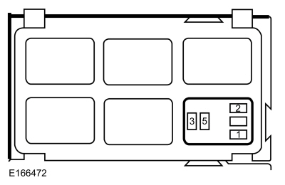 Accessory relay, socket pin 1.
