| 414-00 Charging System - General Information
|
2014 Fiesta
|
| Diagnosis and Testing
|
Procedure revision date:
04/26/2013
|
Charging System - 1.6L EcoBoost (132kW/180PS) - Sigma
Inspection and Verification
Diagnostics in this manual assume a certain skill level and knowledge of Ford-specific diagnostic practices.
REFER to:
Diagnostic Methods
(100-00 General Information, Description and Operation).
for information about these practices.
 WARNING:
Batteries contain sulfuric acid and produce explosive gases. Work in a well-ventilated area. Do not allow the battery to come
in contact with flames, sparks or burning substances. Avoid contact with skin, eyes or clothing. Shield eyes when working
near the battery to protect against possible splashing of acid solution. In case of acid contact with skin or eyes, flush
immediately with water for a minimum of 15 minutes, then get prompt medical attention. If acid is swallowed, call a physician
immediately. Failure to follow these instructions may result in serious personal injury.
WARNING:
Always lift a plastic-cased battery with a battery carrier or with hands on opposite corners. Excessive pressure on the battery
end walls may cause acid to flow through the vent caps, resulting in personal injury and/or damage to the vehicle or battery.
NOTICE:
Do not make jumper connections except as directed. Incorrect connections may damage the voltage regulator test terminals or
fuses.
NOTICE:
Do not allow any metal object to come in contact with the generator housing and internal diode cooling fins. A short circuit
may result and burn out the diodes.
NOTE:
While carrying out any pinpoint test, disregard any Diagnostic Trouble Codes (DTCs) set while following a specific pinpoint
test. After the completion of a test, be sure to clear all Diagnostic Trouble Codes (DTCs) in the
.
NOTE:
All voltage measurements are referenced to the negative (-) battery post unless otherwise specified.
-
Verify the customer concern by operating the charging system.
-
Check the battery condition and state of charge.
REFER to:
Battery
(414-01 Battery, Mounting and Cables, Diagnosis and Testing).
-
Before diagnosing or repairing the charging system inspect the following items:
-
Fusible links
-
Abnormal ignition-off current drain(s).
REFER to:
Battery Drain Check
(414-01 Battery, Mounting and Cables, General Procedures).
-
belt
-
Generator pulley
-
High current
for loose or corroded connections
-
Wiring, terminals or connectors
-
If an obvious cause for an observed or reported concern is found, correct the cause (if possible) before proceeding.
DTC Charts
Diagnostics in this manual assume a certain skill level and knowledge of Ford-specific diagnostic practices.
REFER to:
Diagnostic Methods
(100-00 General Information, Description and Operation).
for information about these practices.
PCM DTC Chart
Symptom Chart
Diagnostics in this manual assume a certain skill level and knowledge of Ford-specific diagnostic practices.
REFER to:
Diagnostic Methods
(100-00 General Information, Description and Operation).
for information about these practices.
Symptom Chart
|
Condition
|
Possible Sources
|
Actions
|
|
System voltage high
|
Refer to the Pinpoint Test
|
GO to Pinpoint Test A
|
|
System voltage low or battery is discharged
|
Refer to the Pinpoint Test
|
GO to Pinpoint Test B
|
|
The generator is noisy
|
Refer to the Pinpoint Test
|
GO to Pinpoint Test C
|
|
Radio interference
|
Refer to the Pinpoint Test
|
GO to Pinpoint Test D
|
|
Charging system warning indicator is never or always on
|
-
-
Generator
-
-
Wiring, terminals or connectors
|
RETRIEVE Diagnostic Trouble Codes (DTCs) from all modules. If any charging system Diagnostic Trouble Codes (DTCs) are found,
Refer to DTC Chart in this section. If no charging system Diagnostic Trouble Codes (DTCs) are found,
REFER to:
Instrumentation, Message Center and Warning Chimes
(413-01 Instrumentation, Message Center and Warning Chimes, Diagnosis and Testing).
|
Pinpoint Tests
System Voltage High
Refer to Wiring Diagrams Cell 12 for schematic and connector information.
NOTE:
P0563 can be set if the vehicle has been recently jump started or the battery has been recently charged. The battery may
become discharged due to excessive load(s) on the charging system from aftermarket accessories or if vehicle accessories have
been operating for an extended period of time without the engine running.
Normal Operation and Fault Conditions
With the engine running, the charging system supplies voltage to the battery and the vehicle electrical system through the
high current
and battery B+ cable. The voltage that is supplied to the vehicle electrical system is used for the operation of the various
vehicle systems and modules. Many modules monitor this voltage and if it rises above or below their calibrated setpoints,
a
sets.
Diagnostic Trouble Code (DTC) Fault Trigger Conditions
|
DTC
|
Description
|
Fault Trigger Conditions
|
|
P0563
|
System Voltage High
|
This
sets if the
detects voltage from the charging system greater than 15.9 volts with vehicle speed above 8 km/h (5 mph).
|
Possible Sources
-
Battery
-
Generator
-
Engine, generator or battery ground
-
-
Wiring, terminals or connectors
Visual Inspection and Diagnostic Pre-checks
-
Inspect high current
for loose or corroded connections.
PINPOINT TEST A : SYSTEM VOLTAGE HIGH
| NOTE:
Make sure battery voltage is greater than 12.2 volts prior to and during this pinpoint test.
|
| NOTE:
Do not have a battery charger attached during vehicle testing.
|
| A1
CHECK BATTERY CONDITION
|
-
Check the battery condition and state of charge.
REFER to:
Battery
(414-01 Battery, Mounting and Cables, Diagnosis and Testing).
-
Disconnect the diagnostic tool.
Does the battery pass the condition test?
| No
|
CHARGE or INSTALL a new battery as necessary.
REFER to:
Battery
(414-01 Battery, Mounting and Cables, Removal and Installation).
|
|
| A2
MONITOR THE GENERATOR VOLTAGE DESIRED (GENVDSD) PID (PARAMETER IDENTIFICATION)
|
-
Using a diagnostic scan tool, view the
GENVDSD.
Does the
indicate 15.9 volts or less?
|
| A3
COMPARE THE GENERATOR VOLTAGE DESIRED (GENVDSD) PID (PARAMETER IDENTIFICATION)
WITH BATTERY VOLTAGE
|
-
With the engine still running at idle, measure and record:
|
Positive Lead
|
Measurement / Action
|
Negative Lead
|
|

|
|
-
Using a diagnostic scan tool, view the
GENVDSD.
Is the recorded battery voltage within ±0.5 volt of the
?
| Yes
|
The system is operating correctly at this time. The concern may have been caused by an intermittently loose or corroded connector.
ADDRESS the root cause of any connector or pin issues.
|
|
| A4
CHECK THE VEHICLE GROUND VOLTAGE DROP
|
-
With the engine still running at idle, headlamps on and heater blower on high, measure:
Is the voltage drop less than 0.5 volt?
| No
|
INSPECT and REPAIR the engine ground, generator ground or the battery ground for corrosion.
|
|
| A5
MONITOR THE GENERATOR VOLTAGE DESIRED (GENVDSD) PID (PARAMETER IDENTIFICATION)
WHILE COMMANDED
|
-
Using a diagnostic scan tool, view the
GENVDSD.
-
Using a diagnostic scan tool, active command, set the
GENVDSD to 14 volts.
-
With the engine still running at idle, measure battery voltage and record.
Is the recorded battery voltage within ±0.5 volt of the
?
|
| A6
CHECK THE GENERATOR OUTPUT
|
-
Increase engine Revolutions Per Minute (RPM) until generator starts to generate output.
-
With the engine running, measure and record:
|
Positive Lead
|
Measurement / Action
|
Negative Lead
|
|
|
|
|
Is the voltage greater than 15.2 volts?
|
| A7
COMPARE THE SUPPLY VOLTAGE (VPWR) PID (PARAMETER IDENTIFICATION)
TO BATTERY VOLTAGE
|
-
With the engine still running at idle, measure and record:
|
Positive Lead
|
Measurement / Action
|
Negative Lead
|
|
|
|
|
-
Using a diagnostic scan tool, view the
VPWR.
Does the
accurately display battery voltage within ±0.5 volt of the recorded battery voltage?
|
| A8
CHECK PCM (POWERTRAIN CONTROL MODULE)
SUPPLY VOLTAGE CIRCUITS
|
-
Measure and record:
|
Positive Lead
|
Measurement / Action
|
Negative Lead
|
|
|
|
|
-
Measure:
|
Positive Lead
|
Measurement / Action
|
Negative Lead
|
|
C1915B-101
|
|
Ground
|
|
C1915B-102
|
|
Ground
|
|
C1915B-103
|
|
Ground
|
Are the voltages within 0.5 volt of the recorded battery voltage?
| No
|
REPAIR the affected circuit(s) for high resistance. CLEAR all Diagnostic Trouble Codes (DTCs) in all modules.
|
|
| A9
CHECK FOR CORRECT PCM (POWERTRAIN CONTROL MODULE)
OPERATION
|
-
Disconnect and inspect all
connectors.
-
Repair:
-
corrosion (install new connector or terminals – clean module pins)
-
damaged or bent pins – install new terminals/pins
-
pushed-out pins – install new pins as necessary
-
Reconnect the
connectors. Make sure they seat and latch correctly.
-
Operate the system and determine if the concern is still present.
Is the concern still present?
| Yes
|
CHECK
for any applicable Technical Service Bulletins (TSBs). If a
exists for this concern, DISCONTINUE this test and FOLLOW the
instructions. If no Technical Service Bulletins (TSBs) address this concern, INSTALL a new
.
REFER to:
Powertrain Control Module (PCM)
(303-14B Electronic Engine Controls - 1.6L EcoBoost (132kW/180PS) - Sigma, Removal and Installation).
CLEAR all Diagnostic Trouble Codes (DTCs) in all modules.
|
| No
|
The system is operating correctly at this time. The concern may have been caused by module connections. ADDRESS the root cause
of any connector or pin issues.
|
|
System Voltage Low or Battery is Discharged
Refer to Wiring Diagrams Cell 12 for schematic and connector information.
Normal Operation and Fault Conditions
With the engine running, the charging system supplies voltage to the battery and the vehicle electrical system through the
high current
and battery B+ cable. The
monitors this B+ voltage through its own voltage supply circuit.
Diagnostic Trouble Code (DTC) Fault Trigger Conditions
|
DTC
|
Description
|
Fault Trigger Conditions
|
|
P0562
|
System Voltage Low
|
If voltage drops 1.5 volts or more below the generator voltage desired (calculated by the
), this
sets after 30 seconds.
|
|
P065B
|
Generator Control Circuit Range/Performance
|
This
sets when the generator reports an internal regulator failure to the
.
|
Possible Sources
-
Excessive ignition-OFF current drain
-
Battery
-
High current
-
Generator
-
-
Wiring, terminals or connectors
Visual Inspection and Diagnostic Pre-checks
-
Inspect for abnormal ignition-off current drain(s).
-
Inspect the battery.
-
Inspect high current
for loose or corroded connections.
-
Inspect the generator clutch.
PINPOINT TEST B : SYSTEM VOLTAGE LOW OR BATTERY IS DISCHARGED
| B1
RETRIEVE PCM (POWERTRAIN CONTROL MODULE)
DIAGNOSTIC TROUBLE CODES (DTCS)
|
-
Using a diagnostic scan tool, perform
self-test.
Is
P065B present?
|
| B2
CHECK BATTERY CONDITION
|
-
Check the battery condition and state of charge.
REFER to:
Battery
(414-01 Battery, Mounting and Cables, Diagnosis and Testing).
Does the battery pass the condition test?
| No
|
INSTALL a new battery.
REFER to:
Battery
(414-01 Battery, Mounting and Cables, Removal and Installation).
|
|
| B3
CHECK THE GENERATOR CONNECTIONS
|
-
Disconnect and inspect all generator connectors.
-
Repair:
-
corrosion (install new connector or terminals – clean module pins)
-
damaged or bent pins – install new terminals/pins
-
pushed-out pins – install new pins as necessary
-
Reconnect the generator connectors. Make sure they seat and latch correctly.
-
Measure and record:
|
Positive Lead
|
Measurement / Action
|
Negative Lead
|
|
|
|
|
-
Measure:
|
Positive Lead
|
Measurement / Action
|
Negative Lead
|
|
C102B-1
|
|
Ground
|
Is the voltage within 0.5 volt of the recorded battery voltage?
| No
|
TIGHTEN or INSTALL a new C102B (B+ nut) as needed.
REFER to:
Generator - 1.6L EcoBoost (132kW/180PS) - Sigma
(414-02 Generator and Regulator, Removal and Installation).
VERIFY high current
MEGA fuse 1 (450A) is OK. If OK, REPAIR the circuit. If not OK, REFER to the Wiring Diagrams manual to identify the possible
causes of the circuit short.
|
|
| B4
CHECK THE VOLTAGE DROP IN THE GENERATOR B+ CIRCUIT
|
-
With the engine running at idle, headlamps on and blower on high, measure:
|
Positive Lead
|
Measurement / Action
|
Negative Lead
|
|
C102B-1
|
|
|
-
Carry out a wiggle test of the generator wiring and connections while measuring voltage drop.
Is the voltage drop less than 0.5 volt?
| No
|
INSPECT and REPAIR any corrosion in the generator B+ circuit or positive battery cable connections.
|
|
| B5
CHECK THE VOLTAGE DROP IN THE VEHICLE GROUNDS
|
-
With the engine still running at idle, headlamps on and heater blower on high, measure:
Is the voltage drop less than 0.5 volt?
| No
|
INSPECT and REPAIR the engine ground, generator ground or the battery ground for corrosion.
|
|
| B6
MONITOR THE GENERATOR VOLTAGE DESIRED (GENVDSD) PID (PARAMETER IDENTIFICATION)
WHILE COMMANDED
|
-
Using a diagnostic scan tool, view the
GENVDSD
.
-
Using a diagnostic scan tool active command, set the
GENVDSD to 14 volts.
-
With the engine still running at idle, measure battery and record:
|
Positive Lead
|
Measurement / Action
|
Negative Lead
|
|
|
|
|
Is the recorded battery voltage within ±0.5 volt of the
?
|
| B7
COMPARE THE SUPPLY VOLTAGE (VPWR) PID (PARAMETER IDENTIFICATION)
TO BATTERY VOLTAGE
|
-
With the engine still running at idle, headlamps on and blower on high, measure and record:
|
Positive Lead
|
Measurement / Action
|
Negative Lead
|
|
|
|
|
-
Using a diagnostic scan tool, view the
VPWR.
Does the
accurately display battery voltage within ±0.5 volt of the recorded battery voltage?
| No
|
REPAIR high resistance or loose connections in the affected
power circuit(s).
|
|
| B8
CHECK PCM (POWERTRAIN CONTROL MODULE)
GROUND FOR HIGH RESISTANCE
|
-
Using a diagnostic scan tool, view
VPWR and record.
-
With the engine still running at idle, turn headlamps on and blower on high.
-
Measure and record:
|
Positive Lead
|
Measurement / Action
|
Negative Lead
|
|
|
|
|
-
Using a diagnostic scan tool, view
VPWR and record.
Does the
read within ±0.5 volt of battery voltage with accessory loads on and off?
| No
|
REPAIR the affected
ground circuit(s).
|
|
| B9
MONITOR THE SUPPLY VOLTAGE (VPWR) PID (PARAMETER IDENTIFICATION)
|
-
NOTE:
Measure battery voltage at the battery.
With the engine still running at idle, turn off all accessory loads.
-
Measure and record:
|
Positive Lead
|
Measurement / Action
|
Negative Lead
|
|
|
|
|
-
Using a diagnostic scan tool, view
VPWR and record.
-
Momentarily accelerate the engine to Wide Open Throttle (WOT) and release. Repeat this step 4-5 times while continuing to
monitor the
.
Does the
stay within 0.5 volt of the recorded battery voltage when the engine Revolutions Per Minute (RPM) are increased?
| Yes
|
The system is operating correctly at this time. The concern may have been caused by a loose or corroded connector. INSPECT
and REPAIR any connector or pin issues found. If no connector or pin issues are found, CARRY OUT the battery drain test.
REFER to:
Battery Drain Check
(414-01 Battery, Mounting and Cables, General Procedures).
|
|
| B10
CHECK FOR CORRECT PCM (POWERTRAIN CONTROL MODULE)
OPERATION
|
-
Disconnect and inspect all
connectors.
-
Repair:
-
corrosion (install new connector or terminals – clean module pins)
-
damaged or bent pins – install new terminals/pins
-
pushed-out pins – install new pins as necessary
-
Reconnect the
connectors. Make sure they seat and latch correctly.
-
Operate the system and determine if the concern is still present.
Is the concern still present?
| Yes
|
CHECK
for any applicable Technical Service Bulletins (TSBs). If a
exists for this concern, DISCONTINUE this test and FOLLOW the
instructions. If no Technical Service Bulletins (TSBs) address this concern, INSTALL a new
.
REFER to:
Powertrain Control Module (PCM)
(303-14B Electronic Engine Controls - 1.6L EcoBoost (132kW/180PS) - Sigma, Removal and Installation).
CLEAR all Diagnostic Trouble Codes (DTCs) in all modules.
|
| No
|
The system is operating correctly at this time. The concern may have been caused by a loose or corroded connector. ADDRESS
the root cause of any connector or pin issues.
|
|
The Generator is Noisy
Normal Operation and Fault Conditions
The generator is belt-driven by the
system. There are several sources of generator noise which include bearing noise, electrical fault noise, generator or belt
pulley misalignment. A generator with certain types of diode or stator failures can also produce an audible noise.
DTC Fault Trigger Conditions
|
DTC
|
Description
|
Fault Trigger Conditions
|
|
P065C
|
Generator Mechanical Performance
|
This
sets when the generator reports an internal mechanical failure.
|
Possible Sources
-
belt
-
Loose bolts/brackets
-
Generator/pulleys
Visual Inspection and Diagnostic Pre-checks
-
Inspect the
belt.
-
Inspect for loose bolts/brackets.
-
Inspect the generator/pulley.
PINPOINT TEST C : THE GENERATOR IS NOISY
| C1
CHECK FOR ACCESSORY DRIVE BELT NOISE AND LOOSE MOUNTING BRACKETS
|
-
Check the
belt and tensioner for damage and correct installation.
REFER to:
Accessory Drive
(303-05B Accessory Drive - 1.6L EcoBoost (132kW/180PS) - Sigma, Diagnosis and Testing).
Is the accessory drive OK?
|
| C2
CHECK THE GENERATOR MOUNTING
|
-
Check the generator mounting for loose bolts or misalignment.
Is the generator mounted correctly?
|
| C3
CHECK THE GENERATOR FOR NOISE
|
-
With the engine running, use a stethoscope or equivalent listening device to probe the generator and the accessory drive area
for unusual mechanical noise.
Is the generator the noise source?
| No
|
REFER to:
Engine
(303-01B Engine - 1.6L EcoBoost (132kW/180PS) - Sigma, Diagnosis and Testing).
to diagnose the source of the engine noise.
|
|
Radio Interference
Refer to Wiring Diagrams Cell 12 for schematic and connector information.
Normal Operation and Fault Conditions
The generator radio suppression equipment reduces interference transmitted through the speakers by the vehicle electrical
system.
NOTE:
If the Original Equipment Manufacturer (OEM)
has been replaced with an aftermarket unit, the vehicle may not pass this test. Return the vehicle to Original Equipment
Manufacturer (OEM) condition before following this pinpoint test.
NOTE:
If the engine is operated at greater than 2,000 Revolutions Per Minute (RPM) momentarily, the generator self-excites. Make
sure when the generator is disconnected the engine rpm stays below 2,000 Revolutions Per Minute (RPM). If it rises above 2,000
Revolutions Per Minute (RPM), turn the ignition to the OFF position and start the test over again.
NOTE:
Inspect for any aftermarket accessories that have been added to the vehicle. Check the wiring for these accessories and be
sure they have not been attached to the generator circuits and are positioned away from the generator wiring.
Possible Sources
-
Generator
-
In-vehicle entertainment system
-
Wiring, terminals or connectors
Visual Inspection and Diagnostic Pre-checks
-
Inspect the generator.
-
Inspect the in-vehicle entertainment system.
PINPOINT TEST D : RADIO INTERFERENCE
| D1
VERIFY THE GENERATOR IS THE SOURCE OF THE AUDIO SYSTEM INTERFERENCE
|
-
Start the engine and allow the engine to idle.
-
Tune the audio system to a station where interference is present.
-
Disconnect Generator C102B
.
-
Start the engine and allow the engine to idle.
Is the interference present with the generator disconnected?
| Yes
|
Diagnose the audio system.
REFER to:
Information and Entertainment System
(415-00C Information and Entertainment System - General Information - Vehicles With: AM/FM/CD/SYNC/Touchscreen Display, Diagnosis and Testing).
|
|
U012D, U042E
Refer to Wiring Diagrams Cell 12 for schematic and connector information.
Normal Operation and Fault Conditions
The charging system supplies voltage to the battery and the vehicle electrical system through the battery B+ cable. The
monitors the generator output through a dedicated
communication circuit. The generator uses this
circuit to communicate the desired voltage setpoint from the
to the internal voltage regulator. The generator also uses this
circuit to communicate the generator load and error conditions to the
.
Diagnostic Trouble Code (DTC) Fault Trigger Conditions
|
DTC
|
Description
|
Fault Trigger Conditions
|
|
U012D
|
Lost Communication With Generator Control Module
|
This
sets if the
does not detect communication through the
circuit. This can be a result of an open or short in the
circuit. This
also sets if the generator B+ circuit is open.
|
|
U042E
|
Invalid Data Received From Generator Control Module
|
This
sets when the
receives invalid data from the generator.
|
Possible Sources
-
Generator
-
Wiring, terminals or connectors
Visual Inspection and Diagnostic Pre-checks
-
Inspect high current
MEGA fuse 1 (450A).
-
Inspect high current
for loose or corroded connections.
PINPOINT TEST E : U012D, U042E
| E1
COMPARE THE GENERATOR B+ CIRCUIT TO BATTERY VOLTAGE
|
-
Measure and record:
|
Positive Lead
|
Measurement / Action
|
Negative Lead
|
|
|
|
|
-
Measure:
|
Positive Lead
|
Measurement / Action
|
Negative Lead
|
|
C102B-1
|
|
Ground
|
Is the voltage within 0.5 volt of the recorded battery voltage?
| No
|
TIGHTEN or INSTALL a new C102B (B+ nut) as needed.
REFER to:
Generator - 1.6L EcoBoost (132kW/180PS) - Sigma
(414-02 Generator and Regulator, Removal and Installation).
VERIFY high current
MEGA fuse 1 (450A) is OK. If OK, REPAIR the circuit. If not OK, REFER to the Wiring Diagrams manual to identify the possible
causes of the circuit short.
|
|
| E2
CHECK THE GENERATOR LIN (LOCAL INTERCONNECT NETWORK)
CIRCUIT FOR A SHORT TO VOLTAGE
|
-
Disconnect Generator C102A
.
-
Measure:
|
Positive Lead
|
Measurement / Action
|
Negative Lead
|
|
C102A-1
|
|
Ground
|
Is any voltage present?
|
| E3
CHECK THE GENERATOR LIN (LOCAL INTERCONNECT NETWORK)
CIRCUIT FOR A SHORT TO GROUND
|
-
Measure:
|
Positive Lead
|
Measurement / Action
|
Negative Lead
|
|
C102A-1
|

|
Ground
|
Is the resistance greater than 10,000 ohms?
|
| E4
CHECK THE GENERATOR LIN (LOCAL INTERCONNECT NETWORK)
CIRCUIT FOR AN OPEN
|
-
Measure:
|
Positive Lead
|
Measurement / Action
|
Negative Lead
|
|
C102A-1
|
|
C1915E-55
|
Is the resistance less than 3 ohms?
| Yes
|
INSTALL a new generator.
REFER to:
Generator - 1.6L EcoBoost (132kW/180PS) - Sigma
(414-02 Generator and Regulator, Removal and Installation).
CLEAR the Diagnostic Trouble Codes (DTCs). REPEAT the
self-test. If
U012D is retrieved again, GO to
E5
|
| No
|
REPAIR the affected circuit.
|
|
| E5
CHECK FOR CORRECT PCM (POWERTRAIN CONTROL MODULE)
OPERATION
|
-
Disconnect and inspect all
connectors.
-
Repair:
-
corrosion (install new connector or terminals - clean module pins)
-
damaged or bent pins - install new terminals/pins
-
pushed-out pins - install new pins as necessary
-
Reconnect the
connectors. Make sure they seat and latch correctly.
-
Operate the system and determine if the concern is still present.
Is the concern still present?
| Yes
|
CHECK
for any applicable Technical Service Bulletins (TSBs). If a
exists for this concern, DISCONTINUE this test and FOLLOW the
instructions. If no Technical Service Bulletins (TSBs) address this concern, INSTALL a new
.
REFER to:
Powertrain Control Module (PCM)
(303-14B Electronic Engine Controls - 1.6L EcoBoost (132kW/180PS) - Sigma, Removal and Installation).
CLEAR all Diagnostic Trouble Codes (DTCs) in all modules.
|
| No
|
The system is operating correctly at this time. The concern may have been caused by loose or corroded connector. ADDRESS the
root cause of any connector or pin issues.
|
|
Copyright © Ford Motor Company
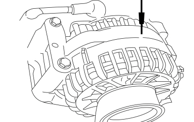 Generator case