 WARNING:
Before beginning any service procedure in this section, refer to Safety Warnings in section 100-00 General Information. Failure
to follow this instruction may result in serious personal injury.
WARNING:
Before beginning any service procedure in this section, refer to Safety Warnings in section 100-00 General Information. Failure
to follow this instruction may result in serious personal injury.
-
REFER to: Safety Belt and Supplemental Restraint System (SRS) Health and Safety Precautions (100-00 General Information, Description and Operation).
- Ignition ON.
- Using a diagnostic scan tool, retrieve ALL Continuous Memory Diagnostic Trouble Codes (CMDTCs).
Is DTC B1317, B1318, B1676, U3003:16 or U3003:17 present in one or more modules AND are any charging system Diagnostic Trouble Codes (DTCs) present in the PCM ?
| Yes |
DIAGNOSE the charging system.
REFER to: Charging System - 1.6L EcoBoost (132kW/180PS) - Sigma (414-00 Charging System - General Information, Diagnosis and Testing). REFER to: Charging System - 1.6L Duratec-16V Ti-VCT (88kW/120PS) - Sigma (414-00 Charging System - General Information, Diagnosis and Testing). |
| No | GO to A2 |
- Ignition OFF.
-
Carry out the Battery Condition Test.
REFER to: Battery (414-01 Battery, Mounting and Cables, Diagnosis and Testing).
Did the battery pass the condition test?
| Yes |
If the battery passed the condition test but required a recharge, DIAGNOSE the charging system.
REFER to: Charging System - 1.6L EcoBoost (132kW/180PS) - Sigma (414-00 Charging System - General Information, Diagnosis and Testing). REFER to: Charging System - 1.6L Duratec-16V Ti-VCT (88kW/120PS) - Sigma (414-00 Charging System - General Information, Diagnosis and Testing). CLEAR all Continuous Memory Diagnostic Trouble Codes (CMDTCs). If the battery passed the condition test and did not require a recharge, GO to A3 |
| No |
INSTALL a new battery.
REFER to: Battery (414-01 Battery, Mounting and Cables, Removal and Installation). CLEAR all Continuous Memory Diagnostic Trouble Codes (CMDTCs). |
- Start the engine.
- Measure the voltage of the battery.
- For DTC U3003:17, turn off all accessories while measuring the battery voltage.
- For DTC U3003:16, turn on headlights and HVAC fan on high while measuring the battery voltage.
Is the voltage between 13 and 15.2 volts?
| Yes |
For
DTC
U3003:16, GO to
A4
For DTC U3003:17, GO to A6 |
| No |
DIAGNOSE the charging system.
REFER to: Charging System - 1.6L EcoBoost (132kW/180PS) - Sigma (414-00 Charging System - General Information, Diagnosis and Testing). REFER to: Charging System - 1.6L Duratec-16V Ti-VCT (88kW/120PS) - Sigma (414-00 Charging System - General Information, Diagnosis and Testing). CLEAR all Continuous Memory Diagnostic Trouble Codes (CMDTCs). |
- Ignition OFF.
-
Depower the
SRS
. Refer to
REFER to: Supplemental Restraint System (SRS) Depowering and Repowering (501-20B Supplemental Restraint System, General Procedures).
-
Disconnect the module with the concern:
- For the RCM , disconnect C310A and C310B.
- For the OCSM , disconnect C3159.
-
For the
RCM
, measure:
Positive Lead Measurement / Action Negative Lead C310A-19 
 CJB
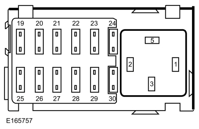
Fuse 20 (10A)
CJB
Fuse 20 (10A)
-
For the
OCSM
, measure:
Positive Lead Measurement / Action Negative Lead C3159-1
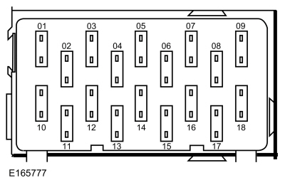 CJB
Fuse 4 (7.5A)
CJB
Fuse 4 (7.5A)
Is the resistance less than 1 ohm?
| Yes | GO to A5 |
| No |
REPAIR the circuit as necessary.
Refer to Wiring Diagrams Cell 5 for schematic and connector information. CLEAR all Continuous Memory Diagnostic Trouble Codes (CMDTCs). |
-
For the
RCM
, measure:
Positive Lead Measurement / Action Negative Lead  RCM
mounting bracket
RCM
mounting bracket
Ground
-
For the
OCSM
, measure:
Positive Lead Measurement / Action Negative Lead C3159-4
Ground
Is the resistance less than 1 ohm?
| Yes | GO to A6 |
| No |
For the
RCM
, VERIFY there is no corrosion between the
RCM
and the mounting surface. VERIFY the fasteners are clean and tightened to specification with no corrosion. REPAIR as necessary.
Refer to Wiring Diagrams Cell 5 for schematic and connector information. For the OCSM , REPAIR the circuit. Refer to Wiring Diagrams Cell 5 for schematic and connector information. CLEAR all Continuous Memory Diagnostic Trouble Codes (CMDTCs). |
- Ignition OFF.
-
Depower the
SRS
.
REFER to: Supplemental Restraint System (SRS) Depowering and Repowering (501-20B Supplemental Restraint System, General Procedures).
-
Disconnect the module with the concern:
- For the RCM , disconnect C310A and C310B (if not previously disconnected).
- For the OCSM , disconnect OCSM C3159 (if not previously disconnected).
-
Check for the following:
- corrosion (install new connector or terminals - clean module pins)
- damaged or bent pins - install new terminals/pins
- pushed-out pins - install new pins as necessary
-
Connect the module with the concern:
- For the RCM , connect C310A and C310B. Make sure the connector seats correctly and engages the Connector Position Assurance (CPA) lever/lock.
- For the OCSM , connect C3159. Make sure the connector seats correctly.
-
Repower the
SRS
.
Do not
prove out the
SRS
at this time.
REFER to: Supplemental Restraint System (SRS) Depowering and Repowering (501-20B Supplemental Restraint System, General Procedures).
- Operate the system and verify the concern is still present.
Is the concern still present?
| Yes |
CHECK
OASIS
for any applicable Technical Service Bulletins (TSBs). If a
TSB
exists for this concern, DISCONTINUE this test and FOLLOW
TSB
instructions.
If no Technical Service Bulletins (TSBs) address this concern, and DTC U3003:16 or U3003:17 was present in the RCM , INSTALL a new RCM . REFER to REFER to: Restraints Control Module (RCM) (501-20B Supplemental Restraint System, Removal and Installation). If no Technical Service Bulletins (TSBs) address this concern, and DTC U3003:16 or U3003:17 was present in the OCSM , INSTALL a new OCSM . REFER to: Occupant Classification System (OCS) Sensor (501-20B Supplemental Restraint System, Removal and Installation). |
| No | The system is operating correctly at this time. The concern may have been caused by a loose or corroded connector. CLEAR all Continuous Memory Diagnostic Trouble Codes (CMDTCs). |