
328-2050-62291 or equivalent

300-ROB75240 or equivalent

STN12270 or equivalent

UVU560000-R
| 303-03B Engine Cooling - 1.6L EcoBoost (132kW/180PS) - Sigma | 2014 Fiesta |
| Diagnosis and Testing | Procedure revision date: 05/15/2013 |
|
|
3-Way HD Antifreeze Coolant Test Kit
328-2050-62291 or equivalent |
|
|
Coolant/Battery Refractometer
300-ROB75240 or equivalent |
|
|
Pressure Tester
STN12270 or equivalent |
|
|
UView® Combustion Leak Tester
UVU560000-R |
Materials
| Material : Motorcraft® Orange Antifreeze/Coolant Concentrated / VC-3-B (WSS-M97B44-D) |
| Material : Motorcraft® Orange Antifreeze/Coolant Prediluted / VC-3DIL-B (WSS-M97B44-D2) |
DTC Chart
Diagnostics in this manual assume a certain skill level and knowledge of Ford-specific diagnostic practices.
REFER to:
Diagnostic Methods
(100-00 General Information, Description and Operation).
PCM DTC Chart
| DTC | Description | Action |
| P0125 | Insufficient Coolant Temp For Closed Loop Fuel Control | GO to Pinpoint Test C |
| P0128 | Coolant Thermostat (Coolant Temp Below Thermostat Regulating Temperature) | GO to Pinpoint Test C |
| P0217 | Engine Coolant Overtemperature Condition | GO to Pinpoint Test B |
| P0480 | Fan 1 Control Circuit | Refer to Powertrain Control/Emissions Diagnosis (PC/ED) manual. |
| P0481 | Fan 2 Control Circuit | Refer to Powertrain Control/Emissions Diagnosis (PC/ED) manual. |
| P0691 | Fan 1 Control Circuit Low | Refer to Powertrain Control/Emissions Diagnosis (PC/ED) manual. |
| P0692 | Fan 1 Control Circuit High | Refer to Powertrain Control/Emissions Diagnosis (PC/ED) manual. |
| P0693 | Fan 2 Control Circuit Low | Refer to Powertrain Control/Emissions Diagnosis (PC/ED) manual. |
| P0694 | Fan 2 Control Circuit High | Refer to Powertrain Control/Emissions Diagnosis (PC/ED) manual. |
| P26B7 | Engine Coolant Bypass Valve "C" Control Circuit/Open | GO to Pinpoint Test D |
| P26BD | Engine Coolant Bypass Valve "D" Control Circuit/Open | GO to Pinpoint Test E |
| All Other PCM Diagnostic Trouble Codes (DTCs) | — |
REFER to: Electronic Engine Controls (303-14B Electronic Engine Controls - 1.6L EcoBoost (132kW/180PS) - Sigma, Diagnosis and Testing). |
Inspection and Verification
 WARNING:
Always allow the engine to cool before opening the cooling system. Do not unscrew the coolant pressure relief cap when the
engine is operating or the cooling system is hot. The cooling system is under pressure; steam and hot liquid can come out
forcefully when the cap is loosened slightly. Failure to follow these instructions may result in serious personal injury.
WARNING:
Always allow the engine to cool before opening the cooling system. Do not unscrew the coolant pressure relief cap when the
engine is operating or the cooling system is hot. The cooling system is under pressure; steam and hot liquid can come out
forcefully when the cap is loosened slightly. Failure to follow these instructions may result in serious personal injury.
NOTICE: The engine cooling system is filled with Motorcraft® Orange Antifreeze/Coolant. Always fill the cooling system with the manufacturer's specified coolant. Chemically flush the cooling system if a non-specified coolant has been used. Failure to follow these instructions may damage the engine or cooling system.
NOTE: During normal vehicle operation, Motorcraft® Orange Antifreeze/Coolant may change color from orange to pink or light red. As long as the engine coolant is clear and uncontaminated, this color change does not indicate the engine coolant has degraded nor does it require the engine coolant to be drained, the system to be flushed, or the engine coolant to be replaced.
NOTE: Vehicles have a pressure relief cap on the degas bottle and no radiator cap.
NOTE: Take note of any coolant odor or steam coming from cooling system components.
If the system coolant is filled correctly and no Diagnostic Trouble Codes (DTCs) associated with fail-safe cooling are retrieved, verify the customer concern by operating the engine to duplicate the condition.Visual Inspection Chart
| Mechanical | Electrical |
|---|---|
|
|
Symptom Chart
Diagnostics in this manual assume a certain skill level and knowledge of Ford-specific diagnostic practices.
REFER to:
Diagnostic Methods
(100-00 General Information, Description and Operation).
| Condition | Possible Sources | Actions |
| Loss of coolant | Refer to the Pinpoint Test | GO to Pinpoint Test A |
| The engine overheats. | Refer to the Pinpoint Test | GO to Pinpoint Test B |
| The engine does not reach normal operating temperature. | Refer to the Pinpoint Test | GO to Pinpoint Test C |
| The block heater does not operate correctly. |
|
|
| The electric cooling fan is inoperative in one or more speeds or does not operate correctly. |
|
Refer to Powertrain Control/Emissions Diagnosis (PC/ED) manual. |
| The electric cooling fan stays on all the time. |
|
Refer to Powertrain Control/Emissions Diagnosis (PC/ED) manual. |
| Noisy electric cooling fan operation. |
|
|
|
|
Pinpoint Tests
Loss of Coolant
Normal operation and Fault Conditions
The engine cooling system is a closed system providing for coolant expansion and contraction as well as changes in pressure as coolant warms and cools with engine operation. Various gaskets, seals, hoses and clamps contain coolant within the cooling system and keep other fluids and contaminants from entering the cooling system. Coolant loss can be attributed to either external or internal leaks anywhere within the cooling system.
Possible Sources
| WARNING:
Always allow the engine to cool before opening the cooling system. Do not unscrew the coolant pressure relief cap when the
engine is operating or the cooling system is hot. The cooling system is under pressure; steam and hot liquid can come out
forcefully when the cap is loosened slightly. Failure to follow these instructions may result in serious personal injury.
|
||||
| A1 CARRY OUT INSPECTION AND VERIFICATION | ||||
Are any concerns present?
|
||||
| A2 CHECK THE ENGINE COOLANT LEVEL AND PRESSURE TEST THE ENGINE COOLING SYSTEM | ||||
|
NOTE: Allow the engine to cool before checking the engine coolant level.
Does the engine cooling system leak externally?
|
||||
| A3 CHECK THE ENGINE COOLANT FOR AN INTERNAL LEAK | ||||
Is engine oil evident in the engine coolant?
|
||||
| A4 CHECK THE ENGINE OIL FOR COOLANT | ||||
Is coolant evident in the oil?
|
||||
| A5 CHECK THE COOLING SYSTEM FOR COMBUSTION GASES | ||||
|
NOTE: Use UView® Combustion Leak Tester part number UVU560000-R or equivalent.
Are combustion gases present?
|
The Engine Overheats
Normal operation and Fault Conditions
The engine cooling system maintains the engine temperature during operation. Correct coolant flow through the engine, radiator and remainder of cooling system passages and components is essential to maintaining a correct engine temperature.
Engine coolant flows primarily from the engine to the radiator circuit and back to the coolant pump. Coolant is sent from the coolant pump through the engine block and cylinder heads. A separate circuit from the engine also feeds the heater core with coolant. The coolant pump circulates the coolant. The coolant thermostat is a control valve actuated by coolant temperature. When the thermostat is closed, coolant flow bypasses the radiator circuit and returns to the coolant pump. When the thermostat is opened, coolant flows through the radiator circuit to transfer engine-generated heat to the outside air.
The engine cooling system incorporates a coolant bypass solenoid valve and a coolant shutoff solenoid valve. Using these two valves, the coolant flow through the engine block can be restricted or completely stagnated. The restriction or stagnation of the coolant flow makes it possible for the engine components to warm up faster during the warm-up phase. The coolant shutoff solenoid valve is normally open and closes when energized to stagnate coolant flow throughout the cooling system if the coolant bypass solenoid valve is also closed. The coolant shutoff solenoid valve blocks or allows coolant flow through the thermostat housing, coolant pump, engine block, heater core, turbocharger, transmission oil cooler, and engine oil cooler. The coolant bypass solenoid valve provides another coolant circuit for the engine block and is normally closed and opens when energized to provide coolant flow between the outlet of the engine block to the thermostat housing. The primary function of this valve is to increase coolant flow through the engine block reducing cooling system pressure and temperature fluctuations during high engine loads. If one or both valves do not open when commanded by the PCM an engine over temperature condition can result.
Engine overheating generally occurs when there is a disruption in the ability to control either coolant flow at the correct rate, the inability to transfer heat from the engine through the coolant (including low coolant) or an inability to transfer engine-generated heat to the outside air through the radiator.
Possible Sources
Diagnostic Trouble Code (DTC) Fault Trigger Conditions
| DTC | Description | Fault Trigger Conditions |
| P0217 | Engine Coolant Overtemperature Condition | Sets in the PCM when an engine overheat condition was sensed by the ECT sensor. |
| B1 CARRY OUT INSPECTION AND VERIFICATION | ||||
Are any concerns present?
|
||||
| B2 CHECK FOR PCM (POWERTRAIN CONTROL MODULE) DTCS | ||||
Is DTC P0217 present?
|
||||
| B3 REVIEW THE PCM (POWERTRAIN CONTROL MODULE) DTCS | ||||
Is DTC P26B7 or P26BD present?
|
||||
| B4 CHECK FOR AN AIRFLOW OBSTRUCTION | ||||
Is an obstruction present?
|
||||
| B5 CHECK THE ENGINE COOLANT LEVEL AND PRESSURE TEST THE COOLING SYSTEM | ||||
Does the engine cooling system leak externally?
|
||||
| B6 CHECK THE ENGINE COOLANT FOR AN INTERNAL LEAK | ||||
Is engine oil evident in the coolant?
|
||||
| B7 CHECK THE ENGINE OIL FOR COOLANT | ||||
Is coolant evident in the oil?
|
||||
| B8 CHECK THE COOLING SYSTEM FOR COMBUSTION GASES | ||||
|
NOTE: Use UView® Combustion Leak Tester part number UVU560000-R or equivalent.
Are combustion gases present?
|
||||
| B9 CHECK COOLANT CONDITION | ||||
Is the coolant condition OK?
|
||||
| B10 CHECK THE ELECTRIC COOLING FAN OPERATION | ||||
Did the electric cooling fan operate?
|
||||
| B11 CHECK THE COOLANT SHUTOFF SOLENOID FOR BEING STUCK CLOSED | ||||
Is coolant flow present?
|
||||
| B12 CHECK THE COOLANT BYPASS SOLENOID VALVE FOR BEING STUCK CLOSED | ||||
Is the bypass hose cool to the touch?
|
||||
| B13 VISUALLY INSPECT THE THERMOSTAT | ||||
Is the thermostat damaged?
|
The Engine Does Not Reach Normal Operating Temperature
Normal operation and Fault Conditions
The engine cooling system maintains engine temperature during operation. Correct coolant flow through the engine, radiator and remainder of cooling system passages and components is essential to maintaining a correct engine temperature.
Engine coolant flows primarily from the engine to the radiator circuit and back to the coolant pump. Coolant is sent from the coolant pump through the engine block and cylinder heads. A separate circuit from the engine also feeds the heater core with coolant. The coolant pump circulates the coolant. The coolant thermostat is a control valve actuated by coolant temperature. When the thermostat is closed, coolant flow bypasses the radiator circuit and returns to the coolant pump. When the thermostat is opened, coolant flows through the radiator circuit in order to transfer engine generated heat to the outside air.
Concerns of engine inability to reach normal operating temperature typically occur when the rate of coolant flow through some coolant circuits (radiator, heater core) is more than expected given the conditions. Heat is not allowed to build in the engine because a heat exchanger is removing too much heat, including the radiator, heater core and oil cooler. In addition, perceived concerns that the engine does not reach normal operating temperature can be related to a low coolant level or trapped air which does not allow for hot coolant to be available at the heater core, an inoperative climate control system, or for concerns perceived or related to an incorrect engine temperature gauge indication.
The engine cooling system incorporates a coolant bypass solenoid valve and a coolant shutoff solenoid valve. Using these two valves, the coolant flow through the engine block can be restricted or completely stagnated. The restriction or stagnation of the coolant flow makes it possible for the engine components to warm up faster during the warm-up phase. The coolant shutoff solenoid valve is normally open and closes when energized to stagnate coolant flow throughout the cooling system if the coolant bypass solenoid valve is closed. The coolant shutoff solenoid valve blocks or allows coolant flow through the thermostat housing, coolant pump, engine block, heater core, turbocharger, transmission oil cooler, and engine oil cooler. The coolant bypass solenoid valve provides another coolant circuit for the engine block and is normally closed and opens when energized to provide coolant flow between the outlet of the engine block to the thermostat housing. The primary function of this valve is to increase coolant flow through the engine block reducing cooling system pressure and temperature fluctuations during high engine loads. The coolant bypass solenoid valve is commanded open during high engine temperatures to provide more cooling. If the coolant bypass solenoid valve mechanically sticks open the engine takes longer to reach operating temperature.
Possible Sources
Diagnostic Trouble Code (DTC) Fault Trigger Conditions
| DTC | Description | Fault Trigger Conditions |
| P0125 | Insufficient Coolant Temp for Closed Loop Fuel Control | Sets in the PCM when the ECT sensor has not achieved the required temperature level to enter closed loop operating conditions within a specified amount of time after starting the engine. |
| P0128 | Coolant Thermostat (Coolant Temp Below Thermostat Regulating Temperature) | Sets in the PCM when the thermostat monitor has not achieved the required engine operating temperature within a specified amount of time after starting the engine. |
| WARNING:
Always allow the engine to cool before opening the cooling system. Do not unscrew the coolant pressure relief cap when the
engine is operating or the cooling system is hot. The cooling system is under pressure; steam and hot liquid can come out
forcefully when the cap is loosened slightly. Failure to follow these instructions may result in serious personal injury.
|
||||
| C1 CARRY OUT INSPECTION AND VERIFICATION | ||||
Were any concerns found?
|
||||
| C2 CHECK FOR DTC (DIAGNOSTIC TROUBLE CODE) P0125 OR P0128 | ||||
Is DTC P0125 or P0128 present?
|
||||
| C3 REVIEW THE PCM (POWERTRAIN CONTROL MODULE) DTCS | ||||
Is DTC P26B7 or P26BD present?
|
||||
| C4 CHECK THE COOLANT LEVEL | ||||
|
NOTE: Allow the engine to cool before checking the coolant expansion tank.
Is the engine coolant level within specification?
|
||||
| C5 CHECK THE COOLANT BYPASS SOLENOID VALVE FOR BEING STUCK OPEN | ||||
Is the coolant hose hot?
|
||||
| C6 CHECK THE ECT (ENGINE COOLANT TEMPERATURE) SENSOR OPERATION | ||||
Is the temperature reading similar to the ECT PID value?
|
P26B7
Refer to Wiring Diagrams Cell 25 for schematic and connector information.
Normal operation and Fault Conditions
The engine cooling system incorporates a coolant bypass solenoid valve and a coolant shutoff solenoid valve. Using these two valves, the coolant flow through the engine block can be restricted or completely stagnated. The restriction or stagnation of the coolant flow makes it possible for the engine components to warm up faster during the warm-up phase. Both solenoid valves are controlled by the PCM via a low side driver. The PCM monitors both solenoids for electrical faults and sets an appropriate DTC .
Possible Sources
Diagnostic Trouble Code (DTC) Fault Trigger Conditions
| DTC | Description | Fault Trigger Conditions |
| P26B7 | Engine Coolant Bypass Valve "C" Control Circuit/Open | The PCM monitors the Engine Coolant Bypass Valve "C" Control Circuit/Open circuit for high and low voltage. The test fails if the voltage exceeds a calibrated limit for a calibrated amount of time. |
| WARNING:
Always allow the engine to cool before opening the cooling system. Do not unscrew the coolant pressure relief cap when the
engine is operating or the cooling system is hot. The cooling system is under pressure; steam and hot liquid can come out
forcefully when the cap is loosened slightly. Failure to follow these instructions may result in serious personal injury.
|
||||||||||
| D1 CHECK THE COOLANT BYPASS SOLENOID VALVE CONNECTOR FOR BEING FULLY SEATED | ||||||||||
Were any concerns found?
|
||||||||||
| D2 CHECK THE COOLANT BYPASS SOLENOID VALVE RESISTANCE | ||||||||||
Is the resistance between 9-12 ohms?
|
||||||||||
| D3 CHECK FOR VOLTAGE TO THE COOLANT BYPASS SOLENOID VALVE | ||||||||||
Is voltage greater than 11 volts?
|
||||||||||
| D4 CHECK THE COOLANT BYPASS SOLENOID VALVE CIRCUIT FOR A SHORT TO POWER | ||||||||||
Is any voltage present?
|
||||||||||
| D5 CHECK THE COOLANT BYPASS SOLENOID VALVE CIRCUIT FOR A SHORT TO GROUND | ||||||||||
Is the greater than 10,000 ohms?
|
||||||||||
| D6 CHECK THE COOLANT BYPASS SOLENOID VALVE CIRCUIT FOR AN OPEN | ||||||||||
Is the resistance less than 3 ohms?
|
||||||||||
| D7 CHECK FOR CORRECT PCM (POWERTRAIN CONTROL MODULE) OPERATION | ||||||||||
Is the concern still present?
|
P26BD
Refer to Wiring Diagrams Cell 25 for schematic and connector information.
Normal operation and Fault Conditions
The engine cooling system incorporates a coolant bypass solenoid valve and a coolant shutoff solenoid valve. Using these two valves, the coolant flow through the engine block can be restricted or completely stagnated. The restriction or stagnation of the coolant flow makes it possible for the engine components to warm up faster during the warm-up phase. Both solenoid valves are controlled by the PCM via a low side driver. The PCM monitors both solenoids for electrical faults and sets an appropriate DTC .
Possible Sources
Diagnostic Trouble Code (DTC) Fault Trigger Conditions
| DTC | Description | Fault Trigger Conditions |
| P26BD | Engine Coolant Bypass Valve "D" Control Circuit/Open | The PCM monitors the Engine Coolant Bypass Valve "D" Control Circuit/Open circuit for high and low voltage. The test fails if the voltage exceeds a calibrated limit for a calibrated amount of time. |
| WARNING:
Always allow the engine to cool before opening the cooling system. Do not unscrew the coolant pressure relief cap when the
engine is operating or the cooling system is hot. The cooling system is under pressure; steam and hot liquid can come out
forcefully when the cap is loosened slightly. Failure to follow these instructions may result in serious personal injury.
|
||||||||||
| E1 CHECK THE COOLANT SHUTOFF SOLENOID VALVE CONNECTOR FOR BEING FULLY SEATED | ||||||||||
Were any concerns found?
|
||||||||||
| E2 CHECK THE COOLANT SHUTOFF SOLENOID VALVE RESISTANCE | ||||||||||
Is the resistance between 9-12 ohms?
|
||||||||||
| E3 CHECK FOR VOLTAGE TO THE COOLANT SHUTOFF SOLENOID VALVE | ||||||||||
Is voltage greater than 11 volts?
|
||||||||||
| E4 CHECK THE COOLANT SHUTOFF SOLENOID VALVE CIRCUIT FOR A SHORT TO POWER | ||||||||||
Is any voltage present?
|
||||||||||
| E5 CHECK THE COOLANT SHUTOFF SOLENOID VALVE CIRCUIT FOR A SHORT TO GROUND | ||||||||||
Is the greater than 10,000 ohms?
|
||||||||||
| E6 CHECK THE COOLANT SHUTOFF SOLENOID VALVE CIRCUIT FOR AN OPEN | ||||||||||
Is the resistance less than 3 ohms?
|
||||||||||
| E7 CHECK FOR CORRECT PCM (POWERTRAIN CONTROL MODULE) OPERATION | ||||||||||
Is the concern still present?
|
Component Tests
Cooling System Pressure Test
WARNING:
Always allow the engine to cool before opening the cooling system. Do not unscrew the coolant pressure relief cap when the
engine is operating or the cooling system is hot. The cooling system is under pressure; steam and hot liquid can come out
forcefully when the cap is loosened slightly. Failure to follow these instructions may result in serious personal injury.
NOTE: Vehicles have a pressure relief cap on the degas bottle and no radiator cap.
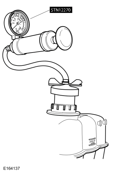
NOTICE: Do not pressurize the cooling system beyond the maximum pressure listed in the specifications table in this section, or cooling system components can be damaged.
NOTE: If the plunger of the pressure tester is pressed too fast, an erroneous pressure reading will result.
Thermostat
Install a new thermostat only after at least one of the following tests and checks have been carried out:
Thermostat Visual Inspection
NOTE: If no damage is found during the inspection, do not attempt to open the thermostat using hot water or other heat sources. This method is not an accurate means to test the function of the thermostat and may damage the thermostat.
If damage is found during the inspection, remove any foreign material or broken pieces and install a new thermostat.Radiator Leak Test, Removed From Vehicle
NOTICE: Never leak test an aluminum radiator in the same water that copper/brass radiators are tested in. Flux and caustic cleaners may be present in the cleaning tank and they will damage aluminum radiators.
NOTE: Clean the radiator before leak testing to avoid contamination of tank.
Copyright © Ford Motor Company
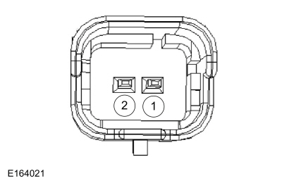 pin 1 (component side)

