| 211-05 Steering Column Switches
|
2014 Fiesta
|
| Diagnosis and Testing
|
Procedure revision date:
05/16/2013
|
Steering Wheel and Column Electrical Components
Charts
Chart
Diagnostics in this manual assume a certain skill level and knowledge of Ford-specific diagnostic practices.
REFER to:
Diagnostic Methods
(100-00 General Information, Description and Operation).
Chart
Diagnostics in this manual assume a certain skill level and knowledge of Ford-specific diagnostic practices.
REFER to:
Diagnostic Methods
(100-00 General Information, Description and Operation).
Module
Chart
Diagnostics in this manual assume a certain skill level and knowledge of Ford-specific diagnostic practices.
REFER to:
Diagnostic Methods
(100-00 General Information, Description and Operation).
Symptom Chart
Symptom Chart: Steering Column Switches
Diagnostics in this manual assume a certain skill level and knowledge of Ford-specific diagnostic practices.
REFER to:
Diagnostic Methods
(100-00 General Information, Description and Operation).
Symptom Chart
|
Condition
|
Possible Sources
|
Actions
|
|
No power in all ignition switch positions - conventional ignition switch
|
-
Refer to the Pinpoint Test
|
|
|
No power in ACC - conventional ignition switch
|
-
Refer to the Pinpoint Test
|
|
|
No power in ON - conventional ignition switch
|
-
Refer to the Pinpoint Test
|
|
|
No power in START - conventional ignition switch
|
-
Refer to the Pinpoint Test
|
-
DIAGNOSE a no-start condition.
REFER to:
Starting System
(303-06A Starting System - 1.6L Duratec-16V Ti-VCT (88kW/120PS) - Sigma, Diagnosis and Testing).
REFER to:
Starting System
(303-06B Starting System - 1.6L EcoBoost (132kW/180PS) - Sigma, Diagnosis and Testing).
|
|
No power in ON - push button ignition switch
|
-
Refer to the Pinpoint Test
|
|
|
KEY NOT DETECTED is displayed
|
-
Refer to the Pinpoint Test
|
-
REFER to:
Passive Anti-Theft System (PATS)
(419-01C Passive Anti-Theft System (PATS) - Vehicles With: Keyless Entry and Push Button Start, Diagnosis and Testing).
|
|
The ignition key cylinder cannot be returned to the OFF position
|
-
Refer to the Pinpoint Test
|
|
|
The ignition key cylinder can be turned to the OFF position when the selector lever is not in PARK
|
-
Refer to the Pinpoint Test
|
|
|
The key cannot be removed from the ignition lock cylinder
|
-
Refer to the Pinpoint Test
|
|
|
The ignition key is hard to turn
|
-
Refer to the Pinpoint Test
|
|
Pinpoint Tests
No Power in All Ignition Switch Positions - Conventional Ignition Switch
Refer to Wiring Diagrams Cell 13 for schematic and connector information.
Normal Operation and Fault Conditions
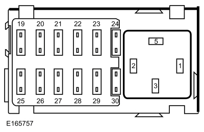
The ignition switch receives fused battery voltage from
fuse 1 (15A). The ignition switch distributes this voltage to various electrical systems depending on the ignition switch
position.
Possible Causes
-
Fuse
-
Wiring, terminals or connectors
-
Ignition switch
Visual Inspection and Diagnostic Pre-checks
-
Inspect the
fuse 1 (15A).
-
Inspect
fuse 5 (60A).
No Power in ACC - Conventional Ignition Switch
Refer to Wiring Diagrams Cell 13 for schematic and connector information.
Normal Operation and Fault Conditions
When the ignition switch is in the ACC position, voltage is provided through
fuse 19 (7.5A) to the
, signaling the ignition system is in ACC mode. The
sends a message over the
to indicate the ignition ACC mode to other modules on the network.
Fault Trigger Conditions
|
|
Description
|
Fault Trigger Conditions
|
|
U300F:00
|
Ignition Input Accessory: No Sub Type Information
|
Sets when the
detects the ignition transitions from OFF to ON and no voltage is detected from the ACC input circuit.
|
Possible Causes
-
Fuse
-
Wiring, terminals or connectors
-
Ignition switch
No Power in ON - Conventional Ignition Switch
Refer to Wiring Diagrams Cell 13 for schematic and connector information.
Normal Operation and Fault Conditions
When the ignition switch is in the ON position, it provides voltage to the
fuses 20 (10A), 21 (7.5A), 22 (7.5A), 23 (7.5A) and to the coil side of the ignition relay. When the ignition relay energizes,
it provides voltage to a variety of other vehicle systems.
The switch side of the ignition relay receives fused battery voltage from the
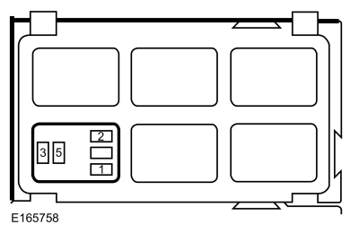
fuse 7 (60A). When the ignition relay energizes, it provides voltage to the remaining vehicle electrical systems that require
power only when the ignition switch is in the ON position.
Possible Causes
-
Wiring, terminals or connectors
-
Ignition relay
-
Ignition switch
Visual Inspection and Diagnostic Pre-checks
-
Inspect
fuse 7 (60A).
-
Inspect the ignition relay.
No Power in START - Conventional Ignition Switch
Refer to Wiring Diagrams Cell 20 for schematic and connector information.
Normal Operation and Fault Conditions
When the ignition switch is turned to the START position, voltage is sent through a single circuit to the
and the
indicating a request to start the vehicle. This circuit does not provide voltage to power any of the vehicle systems.
Possible Sources
PINPOINT TEST D : NO POWER IN START - CONVENTIONAL IGNITION SWITCH
| D1
CHECK FOR A STARTING SYSTEM CONCERN
|
Does the vehicle start?
| Yes
|
RECHECK the ignition switch modes and REFER to the Symptom Chart: Steering Column Switches in this section.
|
| No
|
REFER to Section 303-06.
|
|
No Power in ON - Push-Button Ignition Switch
Refer to Wiring Diagrams Cell 13 for schematic and connector information.
Normal Operation and Fault Conditions
When the ignition is in the ON mode, the
module provides voltage to the coil side of the smart keyless entry ignition relay and the smart keyless entry accessory
relay. When the smart keyless entry ignition relay energizes, battery voltage is provided to the ignition relay and several
fuses in the
. The ignition relay provides power to activate the remaining vehicle electrical systems. When the smart keyless entry accessory
relay energizes, battery voltage is provided to
fuse 19 (7.5A) for the
to recognize the ignition accessory input circuit.
In the event the vehicle does not enter ON or the vehicle does not start, the
may display a message to indicate a possible cause.
Possible Causes
-
Wiring, terminals or connectors
-
Ignition relay
-
Ignition switch
Visual Inspection and Diagnostic Pre-checks
-
Inspect the
fuse 7 (60A).
-
Inspect the ignition relay.
PINPOINT TEST E : NO POWER IN ON - PUSH-BUTTON IGNITION SWITCH
| E1
CHECK THE PASSIVE ENTRY FEATURE OPERATION
|
Does the passive entry feature operate?
|
| E2
CHECK FOR THE NO KEY DETECTED MESSAGE
|
-
With the vehicle in PARK (automatic transmission) or NEUTRAL (manual transmission) and the passive key in the vehicle, press
the START/STOP button while monitoring the message center display.
Is the NO KEY DETECTED message displayed?
| Yes
|
DIAGNOSE the NO KEY DETECTED message.
REFER to:
Passive Anti-Theft System (PATS)
(419-01C Passive Anti-Theft System (PATS) - Vehicles With: Keyless Entry and Push Button Start, Diagnosis and Testing).
|
|
| E3
CHECK FOR IGNITION ON MODE
|
-
Monitor the
display in the center of the instrument panel while attempting to enter ON mode. Indicators on the left side of the display
illuminate to indicate the ignition is in the ON mode.
Does the
display power up?
|
| E4
CHECK FOR COMMUNICATION WITH THE RFA (REMOTE FUNCTION ACTUATOR)
MODULE
|
-
Using a diagnostic scan tool, perform the network test.
Does the
module pass the network test?
| No
|
DIAGNOSE the communication concern.
REFER to:
Communications Network
(418-00 Module Communications Network, Diagnosis and Testing).
|
|
| E5
CHECK FOR RFA (REMOTE FUNCTION ACTUATOR)
MODULE DIAGNOSTIC TROUBLE CODES (DTCS)
|
-
Using a diagnostic scan tool, perform the
module self-test.
Are any Diagnostic Trouble Codes (DTCs) present?
| Yes
|
DIAGNOSE the
module Diagnostic Trouble Codes (DTCs). REFER to the
module
Chart in this section.
|
|
| E6
CHECK THE PUSH-BUTTON IGNITION SWITCH (START_SW_1 AND START_SW_2) PARAMETER IDENTIFICATIONS (PIDS)
|
-
Using a diagnostic scan tool, view the
module Parameter Identifications (PIDs).
-
Using a diagnostic scan tool, monitor the
module Parameter Identifications (PIDs) START_SW_1 and START_SW_2 while pressing and releasing the START/STOP button.
Do the Parameter Identifications (PIDs) change when the START/STOP button is pressed and released?
|
| E7
CHECK THE PUSH-BUTTON IGNITION SWITCH GROUND CIRCUIT FOR AN OPEN
|
-
Disconnect Push-Button Ignition Switch C2195
.
-
Measure:
|
Positive Lead
|
Measurement / Action
|
Negative Lead
|
|
C2195-1
|

|
Ground
|
Is the resistance less than 3 ohms?
|
| E8
CHECK FOR SMART KEYLESS ENTRY IGNITION RELAY OUTPUT
|
|
NOTE:
The previous step indicates the
module has changed the ignition state to ON.
-
Observe the
for illuminated indicators.
Are any indicators illuminated in the
?
|
| E9
CHECK FOR RFA (REMOTE FUNCTION ACTUATOR)
MODULE SMART KEYLESS ENTRY IGNITION RELAY DIAGNOSTIC TROUBLE CODES (DTCS)
|
-
Using a diagnostic scan tool, perform the
module self-test.
Are any Diagnostic Trouble Codes (DTCs) present?
| Yes
|
DIAGNOSE the
module Diagnostic Trouble Codes (DTCs). REFER to the
Module
Chart in this section.
|
|
| E10
CHECK FOR IPC (INSTRUMENT PANEL CLUSTER)
DTC (DIAGNOSTIC TROUBLE CODE)
U300F:00
|
-
Using a diagnostic scan tool, perform the
self-test.
Is
U300F:00 present?
|
| E11
CHECK THE IGNITION RELAY
|
-
Disconnect Ignition Relay.
-
Substitute a known good relay and recheck the operation.
Is the concern still present?
| Yes
|
REMOVE the known good relay. GO to
E12
|
| No
|
REMOVE the known good relay. INSTALL a new ignition relay.
|
|
| E12
CHECK THE IGNITION RELAY SWITCH BJB (BATTERY JUNCTION BOX)
VOLTAGE SUPPLY CIRCUIT FOR AN OPEN
|
-
Measure:
|
Positive Lead
|
Measurement / Action
|
Negative Lead
|
 Ignition relay, cavity 3
|

|
Ground
|
Is the voltage greater than 11 volts?
| No
|
VERIFY
fuse 7 (60A) is OK. If OK, REPAIR the circuit. If not OK, REFER to the Wiring Diagrams manual to identify the possible causes
of the circuit short.
|
|
| E13
CHECK THE IGNITION RELAY COIL VOLTAGE SUPPLY CIRCUIT FOR AN OPEN
|
-
Measure:
|
Positive Lead
|
Measurement / Action
|
Negative Lead
|
|
Ignition relay, cavity 1
|
|
Ground
|
Is the voltage greater than 11 volts?
|
| E14
CHECK THE IGNITION RELAY GROUND CIRCUIT FOR AN OPEN
|
-
Measure:
|
Positive Lead
|
Measurement / Action
|
Negative Lead
|
|
Ignition relay, cavity 2
|
|
Ground
|
Is the resistance less than 3 ohms?
| Yes
|
REPAIR the ignition relay ground circuit for an open.
|
| No
|
REPAIR the ignition relay output circuit for an open.
|
|
| E15
CHECK FOR CORRECT RFA (REMOTE FUNCTION ACTUATOR)
MODULE OPERATION
|
-
Disconnect and inspect all the
module connectors.
-
Repair:
-
corrosion (install new connector or terminals - clean module pins)
-
damaged or bent pins - install new terminals/pins
-
pushed-out pins - install new pins as necessary
-
Reconnect the
module connectors and all other previously disconnected connectors. Make sure they seat and latch correctly.
-
Operate the system and determine if the concern is still present.
Is the concern still present?
| Yes
|
CHECK
for any applicable Technical Service Bulletins (TSBs). If a
exists for this concern, DISCONTINUE this test and FOLLOW the
instructions. If no Technical Service Bulletins (TSBs) address this concern, INSTALL a new
module.
REFER to:
Remote Function Actuator (RFA) Module
(419-10 Multifunction Electronic Modules, Removal and Installation).
|
| No
|
The system is operating correctly at this time. The concern may have been caused by module connections. ADDRESS the root cause
of any connector or pin issues.
|
|
The Ignition Key Cylinder Cannot Be Returned to the OFF Position
Refer to Wiring Diagrams Cell 37 for schematic and connector information.
Normal Operation and Fault Conditions
REFER to:
Steering Wheel and Column Electrical Components - System Operation and Component Description
(211-05 Steering Column Switches, Description and Operation).
Possible Causes
-
Wiring, terminals or connectors
-
Ignition switch
-
Ignition lock cylinder
-
Selector lever assembly
-
PINPOINT TEST F : THE IGNITION KEY CYLINDER CANNOT BE RETURNED TO THE OFF POSITION
| F1
CHECK FOR AN ENERGIZED KEY REMOVAL INHIBIT SOLENOID
|
-
Attempt to rotate the ignition lock cylinder ON and then back to the OFF-LOCK position and remove the key.
Does the ignition lock cylinder rotate to the OFF-LOCK position and the key removed?
|
| F2
CHECK THE IGNITION SWITCH FOR MECHANICAL DAMAGE
|
-
Remove the ignition switch.
REFER to:
Ignition Switch
(211-05 Steering Column Switches, Removal and Installation).
-
Attempt to rotate the ignition lock cylinder to the OFF-LOCK position and remove the ignition key.
Does the ignition lock cylinder rotate to the OFF-LOCK position and can the key be removed?
| Yes
|
INSTALL a new ignition switch.
REFER to:
Ignition Switch
(211-05 Steering Column Switches, Removal and Installation).
|
| No
|
INSTALL a new ignition lock cylinder.
REFER to:
Ignition Lock Cylinder
(501-14 Handles, Locks, Latches and Entry Systems, Removal and Installation).
|
|
| F3
CHECK THE KEY REMOVAL INHIBIT SOLENOID CIRCUIT FOR A SHORT TO GROUND
|
-
Disconnect Ignition Switch C250
.
-
Measure:
|
Positive Lead
|
Measurement / Action
|
Negative Lead
|
|
C250-3
|
|
Ground
|
Is the resistance greater than 10,000 ohms?
| Yes
|
INSTALL a new ignition switch.
REFER to:
Ignition Switch
(211-05 Steering Column Switches, Removal and Installation).
|
|
| F4
ISOLATE THE IPC (INSTRUMENT PANEL CLUSTER)
|
-
Measure:
|
Positive Lead
|
Measurement / Action
|
Negative Lead
|
|
C250-3
|
|
Ground
|
Is the resistance greater than 10,000 ohms?
|
| F5
CHECK THE KEY REMOVAL INHIBIT SOLENOID CIRCUIT FOR A SHORT TO GROUND
|
-
Disconnect Selector Lever Assembly C3245
.
-
Measure:
|
Positive Lead
|
Measurement / Action
|
Negative Lead
|
|
C250-3
|
|
Ground
|
Is the resistance greater than 10,000 ohms?
| Yes
|
INSTALL a new selector lever assembly.
REFER to:
Selector Lever Assembly
(307-05 Automatic Transmission External Controls - Vehicles With: 6-Speed PowerShift Transmission - DPS6/6DCT250, Removal and Installation).
|
|
| F6
CHECK FOR CORRECT IPC (INSTRUMENT PANEL CLUSTER)
OPERATION
|
-
Disconnect and inspect all the
connectors.
-
Repair:
-
corrosion (install new connector or terminals - clean module pins)
-
damaged or bent pins - install new terminals/pins
-
pushed-out pins - install new pins as necessary
-
Reconnect the
connectors and all other previously disconnected connectors. Make sure they seat and latch correctly.
-
Operate the system and determine if the concern is still present.
Is the concern still present?
| Yes
|
CHECK
for any applicable Technical Service Bulletins (TSBs). If a
exists for this concern, DISCONTINUE this test and FOLLOW the
instructions. If no Technical Service Bulletins (TSBs) address this concern, INSTALL a new
.
REFER to:
Instrument Panel Cluster (IPC)
(413-01 Instrumentation, Message Center and Warning Chimes, Removal and Installation).
|
| No
|
The system is operating correctly at this time. The concern may have been caused by module connections. ADDRESS the root cause
of any connector or pin issues.
|
|
The Ignition Key Cylinder Can Be Turned to the OFF Position When the Selector Lever is Not in PARK
Refer to Wiring Diagrams Cell 37 for schematic and connector information.
Normal Operation and Fault Conditions
REFER to:
Steering Wheel and Column Electrical Components - System Operation and Component Description
(211-05 Steering Column Switches, Description and Operation).
Possible Causes
-
Wiring, terminals or connectors
-
Ignition switch
-
Selector lever
PINPOINT TEST G : THE IGNITION KEY CYLINDER CAN BE TURNED TO THE OFF POSITION WHEN THE SELECTOR LEVER IS NOT IN PARK
| G1
CHECK THE KEY INHIBIT SOLENOID CIRCUIT FOR CONTINUITY TO GROUND
|
-
Disconnect Ignition Switch C250
.
-
Measure:
|
Positive Lead
|
Measurement / Action
|
Negative Lead
|
|
C250-3
|
|
Ground
|
Is the resistance less than 3 ohms?
| Yes
|
INSTALL a new ignition switch.
REFER to:
Ignition Switch
(211-05 Steering Column Switches, Removal and Installation).
|
|
| G2
CHECK THE KEY INHIBIT SOLENOID CIRCUIT FOR AN OPEN
|
-
Disconnect Selector Lever Assembly C3245
.
-
Measure:
|
Positive Lead
|
Measurement / Action
|
Negative Lead
|
|
C250-3
|
|
C3245-2
|
Is the resistance less than 3 ohms?
|
| G3
CHECK THE SELECTOR LEVER ASSEMBLY GROUND CIRCUIT FOR AN OPEN
|
-
Measure:
|
Positive Lead
|
Measurement / Action
|
Negative Lead
|
|
C3245-5
|
|
Ground
|
Is the resistance less than 3 ohms?
| Yes
|
INSTALL a new selector lever assembly.
REFER to:
Selector Lever Assembly
(307-05 Automatic Transmission External Controls - Vehicles With: 6-Speed PowerShift Transmission - DPS6/6DCT250, Removal and Installation).
|
|
B108B:23, B108:29 or B108C:23
Refer to Wiring Diagrams Cell 20 for schematic and connector information.
Normal Operation and Fault Conditions
REFER to:
Steering Wheel and Column Electrical Components - System Operation and Component Description
(211-05 Steering Column Switches, Description and Operation).
The push-button ignition switch is a momentary, dual-contact, normally-open switch. The push-button ignition switch inputs
are monitored by the
module by 2 circuits. When the START/STOP button is pressed, both contacts close and both voltage signals are routed to ground.
The 2 circuits are for redundancy. If there is a concern with one of the 2 inputs, the other input provides a ground signal
to allow the vehicle to start and a
sets.
Module
Fault Trigger Conditions
|
|
Description
|
Fault Trigger Conditions
|
|
B108B:23
|
Start Button Circuit "A": Signal Stuck Low
|
Pressing the start/stop switch starts a 120 second timer in the
module. This
sets when the
module detects the signal from C3503B-23 is still pulled low (switched to ground) when the timer expires. Holding the start/stop
button pressed for more than 120 seconds can cause this
to set. This
only sets continuous; not during a module self-test.
|
|
B108B:29
|
Start Button Circuit "A": Signal Invalid
|
When
module detects 5 occurrences of the push-button start ignition switch inputs not corresponding to each other, such as an
open in one of the input circuits, this
sets. This
only sets continuous; not during a module self-test.
|
|
B108C:23
|
Start Button Circuit "B": Signal Stuck Low
|
Pressing the start/stop switch starts a 120 second timer in the
module. This
sets when the
module detects the signal from C3503B-22 is still pulled low (switched to ground) when the timer expires. Holding the start/stop
button pressed for more than 120 seconds can cause this
to set. This
only sets continuous; not during a module self-test.
|
Possible Causes
-
Wiring, terminals or connectors
-
Push-button ignition switch
-
module
PINPOINT TEST H : B108B:23, B108:29 OR B108C:23
| H1
CHECK THE PUSH-BUTTON IGNITION SWITCH
|
-
Disconnect Push-Button Ignition Switch C2195
.
-
Perform the push-button ignition (start/stop) switch component test.
Refer to Wiring Diagrams Cell 149 for schematic and connector information.
Does the push-button ignition switch pass the component test?
| Yes
|
For
B108B:29, GO to
H2
For
B108B:23 or B108C:23, GO to
H3
|
|
| H2
CHECK THE RFA (REMOTE FUNCTION ACTUATOR)
MODULE START/STOP INPUT CIRCUITS FOR AN OPEN
|
-
Disconnect
Module C3503B
.
-
Measure:
|
Positive Lead
|
Measurement / Action
|
Negative Lead
|
|
C3503B-22
|
|
C2195-3
|
|
C3503B-23
|
|
C2195-4
|
Are the resistances less than 3 ohms?
| No
|
REPAIR the circuit in question.
|
|
| H3
CHECK THE RFA (REMOTE FUNCTION ACTUATOR)
MODULE START/STOP INPUT CIRCUIT A FOR A SHORT TO GROUND
|
-
For
B108B:23, measure:
|
Positive Lead
|
Measurement / Action
|
Negative Lead
|
|
C2195-3
|
|
Ground
|
-
For
B108C:23, measure:
|
Positive Lead
|
Measurement / Action
|
Negative Lead
|
|
C2195-4
|
|
Ground
|
Is the resistance greater than 10,000 ohms?
| No
|
REPAIR the circuit in question.
|
|
| H4
CHECK FOR CORRECT RFA (REMOTE FUNCTION ACTUATOR)
MODULE OPERATION
|
-
Disconnect and inspect all the
module connectors.
-
Repair:
-
corrosion (install new connector or terminals - clean module pins)
-
damaged or bent pins - install new terminals/pins
-
pushed-out pins - install new pins as necessary
-
Reconnect the
module connectors and all other previously disconnected connectors. Make sure they seat and latch correctly.
-
Operate the system and determine if the concern is still present.
Is the concern still present?
| Yes
|
CHECK
for any applicable Technical Service Bulletins (TSBs). If a
exists for this concern, DISCONTINUE this test and FOLLOW the
instructions. If no Technical Service Bulletins (TSBs) address this concern, INSTALL a new
module.
REFER to:
Remote Function Actuator (RFA) Module
(419-10 Multifunction Electronic Modules, Removal and Installation).
|
| No
|
The system is operating correctly at this time. The concern may have been caused by module connections. ADDRESS the root cause
of any connector or pin issues.
|
|
B10E7:11, B10E7:12, B10E7:16 or B10E7:17
Refer to Wiring Diagrams Cell 13 for schematic and connector information.
Normal Operation and Fault Conditions
REFER to:
Steering Wheel and Column Electrical Components - System Operation and Component Description
(211-05 Steering Column Switches, Description and Operation).
The
module controls and monitors the coil and switched output sides of the smart keyless entry ignition relay. When the
module activates the ignition ON mode, it activates the relay providing power to the main ignition relay and to the vehicle
electrical systems.
Module
Fault Trigger Conditions
|
|
Description
|
Fault Trigger Conditions
|
|
B10E7:11
|
Ignition On Relay: Circuit Short To Ground
|
Sets when the
module detects a short to ground from the smart keyless entry ignition relay coil circuit.
|
|
B10E7:12
|
Ignition On Relay: Circuit Short To Battery
|
Sets when the
module detects a short to voltage from the smart keyless entry ignition relay coil circuit.
|
|
B10E7:16
|
Ignition On Relay: Circuit Voltage Below Threshold
|
Sets when the
module does not detect voltage from the smart keyless entry ignition relay output when it has activated the relay.
|
|
B10E7:17
|
Ignition On Relay: Circuit Voltage Above Threshold
|
Sets when the
module detects voltage from the smart keyless entry ignition relay output when it has not activated the relay.
|
Possible Causes
-
Wiring, terminals or connectors
-
Smart keyless entry ignition relay
-
module
Visual Inspection and Diagnostic Pre-checks
-
Inspect the
fuse 1 (15A).
PINPOINT TEST I : B10E7:11, B10E7:12, B10E7:16 OR B10E7:17
| I1
CHECK THE SMART KEYLESS ENTRY IGNITION RELAY
|
-
Disconnect Smart Keyless Entry Ignition Relay.
-
Substitute a known good relay.
-
Using a diagnostic scan tool, clear the Diagnostic Trouble Codes (DTCs) and repeat the self-test.
Is the
still present?
| Yes
|
REMOVE the known good relay.
For
B10E7:11, GO to
I2
For
B10E7:12, GO to
I3
For
B10E7:16, GO to
I5
For
B10E7:17, GO to
I9
|
| No
|
REMOVE the known good relay. INSTALL a new smart keyless entry ignition relay.
|
|
| I2
CHECK THE SMART KEYLESS ENTRY IGNITION RELAY COIL VOLTAGE SUPPLY CIRCUIT FOR A SHORT TO GROUND
|
-
Disconnect
Module C3503B
.
-
Measure:
|
Positive Lead
|
Measurement / Action
|
Negative Lead
|
|
C3503B-18
|
|
Ground
|
Is the resistance greater than 10,000 ohms?
|
| I3
CHECK THE SMART KEYLESS ENTRY IGNITION RELAY COIL VOLTAGE SUPPLY CIRCUIT FOR A SHORT TO BATTERY VOLTAGE
|
-
Measure:
|
Positive Lead
|
Measurement / Action
|
Negative Lead
|
|
C3503B-18
|
|
Ground
|
Is any voltage present?
|
| I4
CHECK THE SMART KEYLESS ENTRY IGNITION RELAY COIL VOLTAGE SUPPLY CIRCUIT FOR A SHORT TO THE SMART KEYLESS ENTRY IGNITION RELAY
OUTPUT CIRCUIT
|
-
Measure:
|
Positive Lead
|
Measurement / Action
|
Negative Lead
|
|
C3503B-18
|
|
C3503B-13
|
Is the resistance greater than 10,000 ohms?
|
| I5
CHECK THE SMART KEYLESS ENTRY IGNITION RELAY COIL VOLTAGE SUPPLY CIRCUIT FOR AN OPEN
|
-
Measure:
|
Positive Lead
|
Measurement / Action
|
Negative Lead
|
 Smart keyless entry ignition relay, cavity 1
|
|
C3503B-18
|
Is the resistance less than 3 ohms?
|
| I6
CHECK THE SMART KEYLESS ENTRY IGNITION RELAY COIL GROUND CIRCUIT FOR AN OPEN
|
-
Measure:
|
Positive Lead
|
Measurement / Action
|
Negative Lead
|
|
Smart keyless entry ignition relay, cavity 2
|
|
Ground
|
Is the resistance less than 3 ohms?
|
| I7
CHECK THE SMART KEYLESS ENTRY IGNITION RELAY BATTERY VOLTAGE SUPPLY CIRCUIT FOR AN OPEN
|
-
Measure:
|
Positive Lead
|
Measurement / Action
|
Negative Lead
|
|
Smart keyless entry ignition relay, cavity 3
|
|
Ground
|
Is the voltage greater than 11 volts?
| No
|
VERIFY the
fuse 1 (15A) is OK. If OK, REPAIR the circuit. If not OK, REFER to the Wiring Diagrams manual to identify the possible causes
of the circuit short.
|
|
| I8
CHECK THE SMART KEYLESS ENTRY IGNITION RELAY OUTPUT CIRCUIT FOR AN OPEN
|
-
Measure:
|
Positive Lead
|
Measurement / Action
|
Negative Lead
|
|
Smart keyless entry ignition relay, cavity 5
|
|
C3503B-13
|
Is the resistance less than 3 ohms?
|
| I9
CHECK THE SMART KEYLESS ENTRY IGNITION RELAY OUTPUT FOR A SHORT TO VOLTAGE
|
-
Measure:
|
Positive Lead
|
Measurement / Action
|
Negative Lead
|
|
C3503B-13
|
|
Ground
|
Is any voltage present?
| Yes
|
REFER to the Wiring Diagrams manual to identify the possible causes of the circuit short.
|
|
| I10
CHECK FOR CORRECT RFA (REMOTE FUNCTION ACTUATOR)
MODULE OPERATION
|
-
Disconnect and inspect all the
module connectors.
-
Repair:
-
corrosion (install new connector or terminals - clean module pins)
-
damaged or bent pins - install new terminals/pins
-
pushed-out pins - install new pins as necessary
-
Reconnect the
module connectors and all other previously disconnected connectors. Make sure they seat and latch correctly.
-
Operate the system and determine if the concern is still present.
Is the concern still present?
| Yes
|
CHECK
for any applicable Technical Service Bulletins (TSBs). If a
exists for this concern, DISCONTINUE this test and FOLLOW the
instructions. If no Technical Service Bulletins (TSBs) address this concern, INSTALL a new
module.
REFER to:
Remote Function Actuator (RFA) Module
(419-10 Multifunction Electronic Modules, Removal and Installation).
|
| No
|
The system is operating correctly at this time. The concern may have been caused by module connections. ADDRESS the root cause
of any connector or pin issues.
|
|
U3004:11 or U3004:12
Refer to Wiring Diagrams Cell 13 for schematic and connector information.
Normal Operation and Fault Conditions
REFER to:
Steering Wheel and Column Electrical Components - System Operation and Component Description
(211-05 Steering Column Switches, Description and Operation).
The
module controls and monitors the coil side of the smart keyless entry accessory relay. When the smart keyless entry accessory
relay is energized, voltage is provided to the
for the ignition ACC mode input.
Module
Fault Trigger Conditions
|
|
Description
|
Fault Trigger Conditions
|
|
U3004:11
|
Accessory Power Relay: Circuit Short To Ground
|
Sets when the
module detects a short to ground from the keyless entry accessory relay coil circuit.
|
|
U3004:12
|
Accessory Power Relay: Circuit Short To Battery
|
Sets when the
module detects a short to voltage from the keyless entry accessory relay coil circuit.
|
Possible Causes
-
Wiring, terminals or connectors
-
Smart keyless entry accessory relay
-
module
PINPOINT TEST J : U3004:11 OR U3004:12
| J1
CHECK THE SMART KEYLESS ENTRY ACCESSORY RELAY
|
-
Disconnect Smart Keyless Entry Accessory Relay.
-
Substitute a known good relay.
-
Using a diagnostic scan tool, clear the Diagnostic Trouble Codes (DTCs) and repeat the self-test.
Is the
still present?
| Yes
|
REMOVE the known good relay.
For
U3004:11, GO to
J2
For
U3004:12, GO to
J3
|
| No
|
REMOVE the known good relay. INSTALL a new smart keyless entry accessory relay.
|
|
| J2
CHECK THE SMART KEYLESS ENTRY ACCESSORY RELAY COIL VOLTAGE SUPPLY CIRCUIT FOR A SHORT TO GROUND
|
-
Disconnect
Module C3503C
.
-
Measure:
|
Positive Lead
|
Measurement / Action
|
Negative Lead
|
|
C3503C-8
|
|
Ground
|
Is the resistance greater than 10,000 ohms?
|
| J3
CHECK THE SMART KEYLESS ENTRY ACCESSORY RELAY COIL VOLTAGE SUPPLY CIRCUIT FOR A SHORT TO VOLTAGE
|
-
Measure:
|
Positive Lead
|
Measurement / Action
|
Negative Lead
|
|
C3503C-8
|
|
Ground
|
Is any voltage present?
|
| J4
CHECK FOR CORRECT RFA (REMOTE FUNCTION ACTUATOR)
MODULE OPERATION
|
-
Disconnect and inspect all the
module connectors.
-
Repair:
-
corrosion (install new connector or terminals - clean module pins)
-
damaged or bent pins - install new terminals/pins
-
pushed-out pins - install new pins as necessary
-
Reconnect the
module connectors and all other previously disconnected connectors. Make sure they seat and latch correctly.
-
Operate the system and determine if the concern is still present.
Is the concern still present?
| Yes
|
CHECK
for any applicable Technical Service Bulletins (TSBs). If a
exists for this concern, DISCONTINUE this test and FOLLOW the
instructions. If no Technical Service Bulletins (TSBs) address this concern, INSTALL a new
module.
REFER to:
Remote Function Actuator (RFA) Module
(419-10 Multifunction Electronic Modules, Removal and Installation).
|
| No
|
The system is operating correctly at this time. The concern may have been caused by module connections. ADDRESS the root cause
of any connector or pin issues.
|
|
U300E:62, U300F:62, U300F:00, U3010:62 or U3011:62
Refer to Wiring Diagrams Cell 13 for schematic and connector information.
Normal Operation and Fault Conditions
The
module monitors the push-button ignition switch. When the START/STOP button is pressed, the
module changes the ignition state (OFF to ON or ON to OFF). After receiving this input, the
module activates/deactivates the smart keyless entry ignition relay and the smart keyless entry accessory relay.
The
receives voltage input on separate circuits from the 2 smart keyless entry relays. Based on the input, the
sends an ignition status message to the
module over the
. The
module compares its current ignition state with the ignition status data from the
. If a discrepancy exists, a
sets.
Module
Fault Trigger Conditions
|
|
Description
|
Fault Trigger Conditions
|
|
U300E:62
|
Ignition Input On: Signal Compare Failure
|
Sets when the
module commanded ignition state does not match the
ignition status message received. This can be caused by a communication issue between the
and the
module, a wiring concern in the ignition input to the
or the
module or a failure in either module.
|
|
U300F:62
|
Ignition Input Accessory: Signal Compare Failure
|
|
U3010:62
|
Ignition Input Start: Signal Compare Failure
|
|
U3011:62
|
Ignition Input Off: Signal Compare Failure
|
Fault Trigger Conditions
|
|
Description
|
Fault Trigger Conditions
|
|
U300F:00
|
Ignition Input Accessory: No Sub Type Information
|
Sets when the
detects the ignition has transitioned from OFF to ON and no voltage is detected from the ACC input circuit.
|
Possible Causes
-
Fuse
-
Wiring, terminals or connectors
-
Smart keyless entry accessory relay
-
-
module
Visual Inspection and Diagnostic Pre-checks
-
Inspect the
fuse 19 (7.5A).
PINPOINT TEST K : U300E:62, U300F:62, U300F:00, U3010:62 OR U3011:62
| K1
CARRY OUT THE NETWORK TEST
|
-
Using a diagnostic scan tool, perform the network test.
Does the
pass the network test?
| No
|
DIAGNOSE the communication concern.
REFER to:
Communications Network
(418-00 Module Communications Network, Diagnosis and Testing).
|
|
| K2
CHECK FOR RFA (REMOTE FUNCTION ACTUATOR)
MODULE DTC (DIAGNOSTIC TROUBLE CODE)
B10E7:16
|
-
Using a diagnostic scan tool, perform the
module self-test.
Is
B10E7:16 present?
|
| K3
CHECK THE SMART KEYLESS ENTRY ACCESSORY RELAY
|
-
Disconnect Smart Keyless Entry Accessory Relay.
-
Substitute a known good relay.
-
Using a diagnostic scan tool, clear the Diagnostic Trouble Codes (DTCs) and repeat the
module or
self-test.
Is the
still present?
| Yes
|
REMOVE the known good relay. GO to
K4
|
| No
|
REMOVE the known good relay. INSTALL a new smart keyless entry accessory relay.
|
|
| K4
CHECK FOR IPC (INSTRUMENT PANEL CLUSTER)
DTC (DIAGNOSTIC TROUBLE CODE)
U300E:00, U300F:00 OR U3010:01
|
-
Connect Smart Keyless Entry Accessory Relay.
-
Using a diagnostic scan tool, perform the
self-test.
Is
U300E:00, U300F:00 or U3010:01 present?
|
| K5
VERIFY THE DTC (DIAGNOSTIC TROUBLE CODE)
SETTING CONDITION
|
-
Measure:
|
Positive Lead
|
Measurement / Action
|
Negative Lead
|
|
C220A-15
|
|
Ground
|
Is the voltage greater than 11 volts?
| No
|
VERIFY the
fuse 19 (7.5A) is OK. If OK, GO to
K6
If not OK, REFER to the Wiring Diagrams manual to identify the possible causes of the circuit short.
|
|
| K6
CHECK THE IPC (INSTRUMENT PANEL CLUSTER)
ACCESSORY INPUT FOR AN OPEN
|
-
Disconnect Smart Keyless Entry Accessory Relay.
-
Measure:
|
Positive Lead
|
Measurement / Action
|
Negative Lead
|
|
C220A-15
|
|
 Smart keyless entry accessory relay, cavity 5
|
Is the resistance less than 3 ohms?
|
| K7
ISOLATE THE IPC (INSTRUMENT PANEL CLUSTER)
ACCESSORY INPUT OPEN
|
-
Disconnect
Fuse 19 (7.5A).
-
Measure:
|
Positive Lead
|
Measurement / Action
|
Negative Lead
|
|
Smart keyless entry accessory relay, cavity 5
|
|
fuse 19 (7.5A)
|
Is the resistance less than 3 ohms?
| Yes
|
REPAIR the accessory input circuit between the
fuse 19 (7.5A) and the
for an open.
|
| No
|
REPAIR the accessory input circuit between the
fuse 19 (7.5A) and the and the smart keyless entry accessory relay for an open.
|
|
| K8
CHECK THE SMART KEYLESS ENTRY ACCESSORY BATTERY VOLTAGE SUPPLY CIRCUIT FOR AN OPEN
|
-
Measure:
|
Positive Lead
|
Measurement / Action
|
Negative Lead
|
|
Smart keyless entry accessory relay, cavity 3
|
|
Ground
|
Is the voltage greater than 11 volts?
|
| K9
CHECK THE SMART KEYLESS ENTRY ACCESSORY RELAY COIL GROUND CIRCUIT FOR AN OPEN
|
-
Measure:
|
Positive Lead
|
Measurement / Action
|
Negative Lead
|
|
Smart keyless entry ignition relay, cavity 2
|
|
Ground
|
Is the resistance less than 3 ohms?
|
| K10
CHECK THE SMART KEYLESS ENTRY ACCESSORY RELAY COIL VOLTAGE SUPPLY CIRCUIT FOR AN OPEN
|
-
Measure:
|
Positive Lead
|
Measurement / Action
|
Negative Lead
|
|
Smart keyless entry ignition relay, cavity 1
|
|
C3503C-8
|
Is the resistance less than 3 ohms?
|
| K11
CHECK THE STARTING SYSTEM FOR CORRECT OPERATION
|
Does the vehicle start?
| No
|
DIAGNOSE the no-start concern.
REFER to:
Starting System
(303-06A Starting System - 1.6L Duratec-16V Ti-VCT (88kW/120PS) - Sigma, Diagnosis and Testing).
REFER to:
Starting System
(303-06B Starting System - 1.6L EcoBoost (132kW/180PS) - Sigma, Diagnosis and Testing).
|
|
| K12
CHECK THE IPC (INSTRUMENT PANEL CLUSTER)
ACCESSORY INPUT FOR A SHORT TO VOLTAGE
|
-
Measure:
|
Positive Lead
|
Measurement / Action
|
Negative Lead
|
|
C220A-15
|
|
Ground
|
Is any voltage present?
|
| K13
ISOLATE THE IPC (INSTRUMENT PANEL CLUSTER)
ACCESSORY INPUT SHORT TO VOLTAGE
|
-
Disconnect
Fuse 19 (7.5A).
-
Measure:
|
Positive Lead
|
Measurement / Action
|
Negative Lead
|
|
C220A-15
|
|
Ground
|
Is any voltage present?
| Yes
|
REPAIR the accessory input circuit between the
fuse 19 (7.5A) and the
for a short to voltage.
|
| No
|
REPAIR the accessory input circuit between the
fuse 19 (7.5A) and the and the smart keyless entry accessory relay for a short to voltage.
|
|
| K14
CHECK THE RFA (REMOTE FUNCTION ACTUATOR)
MODULE START REQUEST CIRCUIT FOR A SHORT TO VOLTAGE
|
-
Disconnect
Module C3503C
.
-
Measure:
|
Positive Lead
|
Measurement / Action
|
Negative Lead
|
|
C3503C-6
|
|
Ground
|
Is any voltage present?
|
| K15
CHECK FOR CORRECT IPC (INSTRUMENT PANEL CLUSTER)
OPERATION
|
-
Disconnect and inspect all the
connectors.
-
Repair:
-
corrosion (install new connector or terminals - clean module pins)
-
damaged or bent pins - install new terminals/pins
-
pushed-out pins - install new pins as necessary
-
Reconnect the
connectors and all other previously disconnected connectors. Make sure they seat and latch correctly.
-
Operate the system and determine if the concern is still present.
Is the concern still present?
| Yes
|
CHECK
for any applicable Technical Service Bulletins (TSBs). If a
exists for this concern, DISCONTINUE this test and FOLLOW the
instructions. If no Technical Service Bulletins (TSBs) address this concern, INSTALL a new
.
REFER to:
Instrument Panel Cluster (IPC)
(413-01 Instrumentation, Message Center and Warning Chimes, Removal and Installation).
|
| No
|
The system is operating correctly at this time. The concern may have been caused by module connections. ADDRESS the root cause
of any connector or pin issues.
|
|
| K16
CHECK FOR CORRECT RFA (REMOTE FUNCTION ACTUATOR)
MODULE OPERATION
|
-
Disconnect and inspect all the
module connectors.
-
Repair:
-
corrosion (install new connector or terminals - clean module pins)
-
damaged or bent pins - install new terminals/pins
-
pushed-out pins - install new pins as necessary
-
Reconnect the
module connectors and all other previously disconnected connectors. Make sure they seat and latch correctly.
-
Operate the system and determine if the concern is still present.
Is the concern still present?
| Yes
|
CHECK
for any applicable Technical Service Bulletins (TSBs). If a
exists for this concern, DISCONTINUE this test and FOLLOW the
instructions. If no Technical Service Bulletins (TSBs) address this concern, INSTALL a new
module.
REFER to:
Remote Function Actuator (RFA) Module
(419-10 Multifunction Electronic Modules, Removal and Installation).
|
| No
|
The system is operating correctly at this time. The concern may have been caused by module connections. ADDRESS the root cause
of any connector or pin issues.
|
|
B1142:13 or U300E:00
Refer to Wiring Diagrams Cell 13 for schematic and connector information.
Normal Operation and Fault Conditions
For vehicles with a conventional ignition switch, the
and the
share ignition ON status over the
. When the ignition status is ON, they also monitor an ignition ON input circuit for voltage. If the
message does not match the input circuit status, a
sets.
For vehicles with a push-button ignition switch, the
and the
receive ignition ON status from the
module over the
. When the ignition status is ON, they also monitor an ignition ON input circuit for voltage. If the
message does not match the input circuit status, a
sets.
Fault Trigger Conditions
|
|
Description
|
Fault Trigger Conditions
|
|
B1142:13
|
Ignition Status 1: Circuit Open
|
Sets when the
receives a message from the
or
module indicating the ignition state is on and the input from the ignition ON circuit does not correspond (such as an open
circuit).
|
Fault Trigger Conditions
|
|
Description
|
Fault Trigger Conditions
|
|
U300E:00
|
Ignition Input On: No Sub Type Information
|
Sets when the
receives a message from the
module indicating the ignition state is on and the input from the ignition ON circuit does not correspond (such as an open
circuit).
|
Possible Causes
-
Fuse
-
Wiring, terminals or connectors
-
-
Visual Inspection and Diagnostic Pre-checks
-
Inspect the
fuse 21 (7.5A).
PINPOINT TEST L : B1142:13 OR U300E:00
| L1
VERIFY THE CONCERN IS PRESENT
|
-
Using a diagnostic scan tool, clear the
and
Diagnostic Trouble Codes (DTCs).
-
Using a diagnostic scan tool, repeat the
and
self-test.
Is
B1142:13 or
U300E:00 present?
| Yes
|
If both DTCs are present, VERIFY the
fuse 21 (7.5A) is OK. If OK, REPAIR the ignition ON voltage supply circuit for an open. If not OK, REFER to the Wiring Diagrams
manual to identify the possible causes of the circuit short.
For
B1142:13, GO to
L2
For
U300E:00, GO to
L3
|
| No
|
The system is operating correctly. The cause may have been a previously low battery voltage concern.
|
|
| L2
CHECK THE IGNITION ON INPUT CIRCUIT FOR AN OPEN TO THE BCM (BODY CONTROL MODULE)
|
-
Measure:
|
Positive Lead
|
Measurement / Action
|
Negative Lead
|
|
C2280B-6
|
|
Ground
|
Is the voltage greater than 11 volts?
|
| L3
CHECK THE IGNITION ON INPUT CIRCUIT FOR AN OPEN TO THE IPC (INSTRUMENT PANEL CLUSTER)
|
-
Measure:
|
Positive Lead
|
Measurement / Action
|
Negative Lead
|
|
C220A-4
|
|
Ground
|
Is the voltage greater than 11 volts?
|
| L4
CHECK FOR CORRECT IPC (INSTRUMENT PANEL CLUSTER)
OPERATION
|
-
Disconnect and inspect all the
connectors.
-
Repair:
-
corrosion (install new connector or terminals - clean module pins)
-
damaged or bent pins - install new terminals/pins
-
pushed-out pins - install new pins as necessary
-
Reconnect the
connectors and all other previously disconnected connectors. Make sure they seat and latch correctly.
-
Operate the system and determine if the concern is still present.
Is the concern still present?
| Yes
|
CHECK
for any applicable Technical Service Bulletins (TSBs). If a
exists for this concern, DISCONTINUE this test and FOLLOW the
instructions. If no Technical Service Bulletins (TSBs) address this concern, INSTALL a new
.
REFER to:
Instrument Panel Cluster (IPC)
(413-01 Instrumentation, Message Center and Warning Chimes, Removal and Installation).
|
| No
|
The system is operating correctly at this time. The concern may have been caused by module connections. ADDRESS the root cause
of any connector or pin issues.
|
|
| L5
CHECK FOR CORRECT BCM (BODY CONTROL MODULE)
OPERATION
|
-
Disconnect and inspect all the
connectors.
-
Repair:
-
corrosion (install new connector or terminals - clean module pins)
-
damaged or bent pins - install new terminals/pins
-
pushed-out pins - install new pins as necessary
-
Reconnect the
connectors and all other previously disconnected connectors. Make sure they seat and latch correctly.
-
Operate the system and determine if the concern is still present.
Is the concern still present?
| Yes
|
CHECK
for any applicable Technical Service Bulletins (TSBs). If a
exists for this concern, DISCONTINUE this test and FOLLOW the
instructions. If no Technical Service Bulletins (TSBs) address this concern, INSTALL a new
.
REFER to:
Body Control Module (BCM)
(419-10 Multifunction Electronic Modules, Removal and Installation).
|
| No
|
The system is operating correctly at this time. The concern may have been caused by module connections. ADDRESS the root cause
of any connector or pin issues.
|
|
U3010:01
Refer to Wiring Diagrams Cell 13 for schematic and connector information.
Normal Operation and Fault Conditions
The
monitors various circuits and performs certain checks during the self-test. If voltage from the ignition switch START input
is detected during the
self-test, a
sets.
Fault Trigger Conditions
|
|
Description
|
Fault Trigger Conditions
|
|
U3010:01
|
Ignition Input Start: General Electrical Failure
|
Sets when the
detects voltage from the ignition START input circuit during the
self-test.
|
Possible Causes
-
Wiring, terminals or connectors
-
PINPOINT TEST M : U3010:01
| M1
CHECK THE IPC (INSTRUMENT PANEL CLUSTER)
IGNITION START INPUT CIRCUIT FOR A SHORT TO VOLTAGE
|
-
Measure:
|
Positive Lead
|
Measurement / Action
|
Negative Lead
|
|
C220A-9
|
|
Ground
|
Is any voltage present?
| Yes
|
REFER to the Wiring Diagrams manual to identify the possible causes of the circuit short.
|
|
| M2
CHECK FOR CORRECT IPC (INSTRUMENT PANEL CLUSTER)
OPERATION
|
-
Disconnect and inspect all the
connectors.
-
Repair:
-
corrosion (install new connector or terminals - clean module pins)
-
damaged or bent pins - install new terminals/pins
-
pushed-out pins - install new pins as necessary
-
Reconnect the
connectors and all other previously disconnected connectors. Make sure they seat and latch correctly.
-
Operate the system and determine if the concern is still present.
Is the concern still present?
| Yes
|
CHECK
for any applicable Technical Service Bulletins (TSBs). If a
exists for this concern, DISCONTINUE this test and FOLLOW the
instructions. If no Technical Service Bulletins (TSBs) address this concern, INSTALL a new
.
REFER to:
Instrument Panel Cluster (IPC)
(413-01 Instrumentation, Message Center and Warning Chimes, Removal and Installation).
|
| No
|
The system is operating correctly at this time. The concern may have been caused by module connections. ADDRESS the root cause
of any connector or pin issues.
|
|
Copyright © Ford Motor Company
 CJB
fuse 1 (15A)
CJB
fuse 1 (15A)
