| The Georgetown Branch : Layout Below are some JPGs of designs I created using Sandia Software's Cadrail 7.11. Click on an image to enlarge. |
|
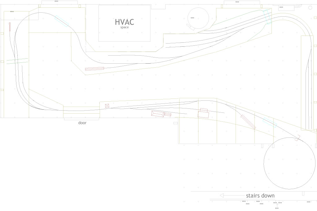
| Layout: Upper Level- Geo. Jct. to Dalecarlia Tunnel Posted: 2/21/06 Locals originate in staging yard on the right side which represents Eckington in Washington DC. Proceeds to Geo. Jct. and down the branch. Across Rock Creek and into Chevy Chase where there is a fuel dealer & team track. Bethesda is the major industrial area at the bottom and has several industries and switching situations. Dalecarlia Tunnel is in the lower right where the train proceeds onto the Helix to the lower level. |
 |
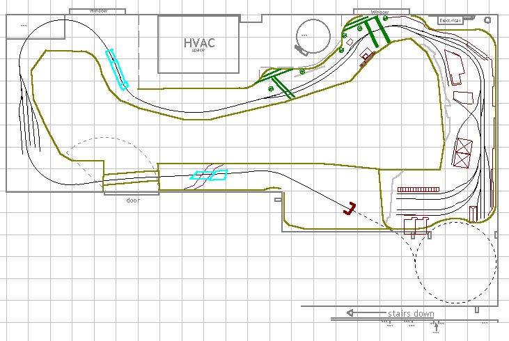
| Layout: Lower Level- Dalecarlia Tunnel to Georgetown Posted: 11/24/03 Begins at Dalecarlia Tunnel, passes by the DC Water Treatment facilities, down the piedmont and across the C&O Canal, and terminates in Georgetown at the waterfront. I think I will have to rework the Georgetown waterfront area because in the era I want to model (1948-ish) the "new" yard had been built. This yard would be located right smack dab in the middle of my plan of G-town. I'm not sure how I'll do this, but I'm definitely going to rework it. |
 without key 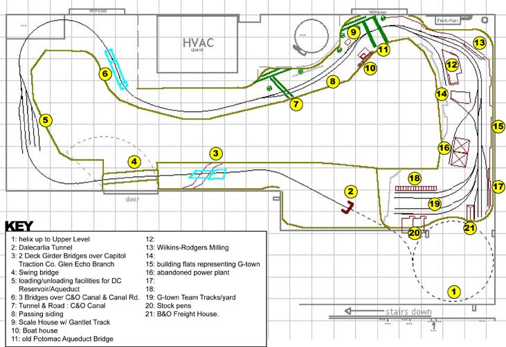 with key |
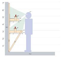
| Layout Height Study Posted: 10/11/2005 Some discussion about the layout height on my model train club email list yielded this diagram which I made to illustrate the proposed heights for the benchwork. |
 Click to open PDF |
| Helix design, part 2 Posted: 01/18/05 After Kelly referred me to an article in the recent Railroad Model Craftsman magazine on how to build a helix out of trapezoidal shapes, with no curve cutting involved, I thought "what a great idea!" So, I used the design I made in CadRail and built on it. Using the top view and the magazine article as a guide, I drew trapezoidal shapes around the plan, cut them up and shaped them to fit in my space. Since I do have a tight space, this design is modified a bit from the original in the magazine. But, overall, it looks promising. The dotted red lines indicate the borders of each board, which is identical in size. The lines in the center are just reference lines for getting the angle right. The squares are support pillars, either 2x2s or 1x1s. |
 Helix design |
| DCC Purchase List Posted: 10/11/2005 Here are my considerations for the DCC system I will purchase for my layout, updated! |
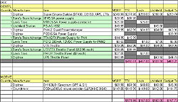 Click to open PDF |
| Layout: How I designed a Helix using Cadrail 7.11 Posted: 12/13/04 The Helix will be the first element of the layout that I construct since it will be tucked away under a staircase, out of the way. I wanted to design it in Cadrail so that I could visualize it in 3D. Since I had no 3D experience, this proved to be a learning experience. I've written it up into a little article available for download as a PDF. Click Here for a copy. (* Right-Click and select Save As) |
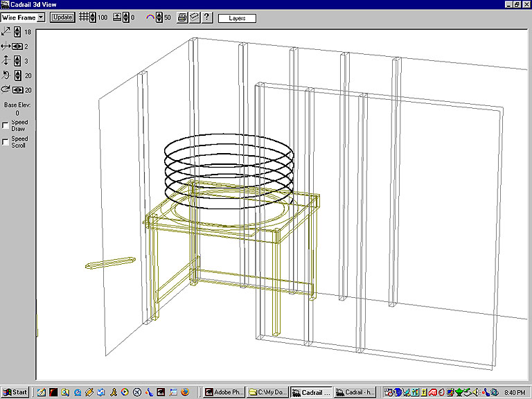 Helix screencap |
| For Old Track Plans, click HERE home | news | history | layout | equipment | gallery | links | contact |
|