303-00 Engine System - General Information 2014 Fiesta
Diagnosis and Testing Procedure revision date: 08/13/2013

Engine

Inspection and Verification - Engine Performance

NOTE: There are 2 diagnostic paths that can be followed depending on the type of engine concern. Carry out Inspection and Verification - Engine Performance or Inspection and Verification - NVH .

  1. Verify the customer concern.
  1. Visually inspect for obvious signs of mechanical or electrical damage.
  1. If an obvious cause for an observed or reported concern is found, correct the cause (if possible) before proceeding to the next step.
  1. NOTE: Make sure to use the latest scan tool software release.

    If the cause is not visually evident, connect the scan tool to the DLC .
  1. NOTE: The VCM LED prove out confirms power and ground from the DLC are provided to the VCM .

    If the scan tool does not communicate with the VCM :
  1. If the scan tool does not communicate with the vehicle:
  1. Carry out the network test.
  1. Clear the continuous DTCs and carry out the self-test diagnostics for the PCM .
  1. If the DTCs retrieved are related to the concern, go to the DTC Chart.
    REFER to: Electronic Engine Controls (303-14A Electronic Engine Controls - 1.6L Duratec-16V Ti-VCT (88kW/120PS) - Sigma, Diagnosis and Testing).
    or REFER to: Electronic Engine Controls (303-14B Electronic Engine Controls - 1.6L EcoBoost (132kW/180PS) - Sigma, Diagnosis and Testing).
    or REFER to: Electronic Engine Controls (303-14C) .

  1. If no DTCs related to the concern are retrieved, GO to Symptom Chart - Engine Performance.

Inspection and Verification - NVH

  1. NVH symptoms should be identified using the diagnostic tools and techniques that are available. For a list of these techniques, tools, an explanation of their uses and a glossary of common terms,
    REFER to: Noise, Vibration and Harshness (NVH) (100-04 Noise, Vibration and Harshness, Diagnosis and Testing).
    Since it is possible that any one of multiple systems may be the cause of the symptom, it may be necessary to use a process of elimination type of diagnostic approach to pinpoint the responsible system.
  1. Verify the customer concern by operating the engine to duplicate the condition.
  1. Check the engine oil level and check the oil for contamination. Low engine oil level or contaminated oil are a common cause of engine noise. If the oil is contaminated, the source of the contamination must be identified and repaired as necessary.
  1. Visually inspect for obvious signs of mechanical damage.
  1. If the inspection reveals obvious concerns that can be readily identified, repair as necessary.
  1. NOTE: Make sure to use the latest scan tool software release.

    If the cause is not visually evident, connect the scan tool to the DLC .
  1. NOTE: The VCM LED prove out confirms power and ground from the DLC are provided to the VCM .

    If the scan tool does not communicate with the VCM :
  1. If the scan tool does not communicate with the vehicle:
  1. Carry out the network test.
  1. Clear the continuous DTCs and carry out the self-test diagnostics for the PCM .
  1. If the DTCs retrieved are related to the concern, go to the DTC Chart.
    REFER to: Electronic Engine Controls (303-14A Electronic Engine Controls - 1.6L Duratec-16V Ti-VCT (88kW/120PS) - Sigma, Diagnosis and Testing).
    or REFER to: Electronic Engine Controls (303-14B Electronic Engine Controls - 1.6L EcoBoost (132kW/180PS) - Sigma, Diagnosis and Testing).
    or REFER to: Electronic Engine Controls (303-14C) .

  1. If no DTCs related to the concern are retrieved, continue the inspection and verification if a noise concern is related to the engine. For vibration concerns and noise concerns such as powertrain mounts, air intake system and starter GO to Symptom Chart - NVH .

In some cases, a noise may be a normal characteristic of that engine type. In other cases the noise may require further investigation. Comparing the noise to a similar year/model vehicle equipped with the same engine will aid in determining if the noise is normal or abnormal.

Once a customer concern has been identified as an abnormal engine noise, it is critical to determine the location of the specific noise. Use the EngineEAR/ChassisEAR or stethoscope (the noise will always be louder closer to the noise source) to isolate the location of the noise to one of the following areas.

Fuel injector noise

A common source of an engine ticking noise can be related to the fuel injection pump Gasoline Turbocharged Direct Injection (GTDI) engine or fuel injector(s). This is normal engine noise that can be verified by listening to another vehicle. If the injector noise is excessive or irregular, use the EngineEAR/ChassisEAR or stethoscope to isolate the noise to a specific fuel injector.

Upper end engine noise

A common source of upper end engine noise (ticking, knocking or rattle) include the camshaft(s) and valve train. Upper end engine noise can be determined using the EngineEAR/ChassisEAR or stethoscope on the valve cover bolts. If the noise is loudest from the valve cover bolts, then the noise is upper end. The EngineEAR/ChassisEAR or stethoscope can be used to further isolate the noise to the specific cylinder bank and cylinder. Removal of the valve covers will be required to pinpoint the source of the noise.

Lower end engine noise

A common source of lower end engine noise (ticking or knocking) include the crankshaft, connecting rod(s) and bearings. Lower end noises can be determined by using the oil pan or lower cylinder block. If the noise is loudest from these areas, then the noise is lower end. If an engine noise is isolated to the lower end, some disassembly of the engine may be required to inspect for damage or wear.

Front of engine noise

A common source of noise from the front of the engine (squeal, chirp, whine or hoot) is the FEAD components. To isolate FEAD noise, carry out the Engine Accessory Test.
REFER to: Noise, Vibration and Harshness (NVH) (100-04 Noise, Vibration and Harshness, Diagnosis and Testing).

Some other noises from the front of the engine (ticking, tapping or rattle) may be internal to the engine. Use the EngineEAR/ChassisEAR or stethoscope on the engine front cover to determine if the noise is internal to the engine. Removal of the engine front cover may be necessary to inspect internal engine components.

Rear of engine noise

A common source of noise from the rear of the engine (knocking) is the flywheel/flexplate. Inspection of the flywheel/flexplate will be necessary.

Turbocharger noise (Gasoline Turbocharged Direct Injection (GTDI) engine)

A common source of noise is the turbocharger. Some whine or air rush noise is an acceptable condition.

  1. After the noise is localized, note the characteristics of the noise, including type of noise, frequency and conditions when the noise occurs and GO to Symptom Chart - NVH .

Symptom Chart - Engine Performance

Symptom Chart - Engine Performance
Symptom Possible Sources Action
  • Difficult starting
  • Inoperative or damaged ignition system
  • Air or vacuum leak
  • Inoperative or damaged fuel system
  • Inoperative or damaged starting system
  • Refer to the appropriate section in Group 303 for the procedure. Refer to Powertrain Control/Emissions Diagnosis (PC/ED) manual.
  • Damaged charging system/ battery
  • Burnt valve
  • INSTALL a new cylinder head. TEST the system for normal operation after the repair.
  • Worn piston
  • INSTALL a new piston. TEST the system for normal operation after the repair.
  • Worn piston rings
  • INSTALL new piston rings. TEST the system for normal operation after the repair.
  • Worn cylinder
  • INSTALL a new cylinder block. TEST the system for normal operation after the repair.
  • Damaged head gasket
  • INSTALL a new cylinder head gasket. TEST the system for normal operation after the repair.
  • Inoperative or damaged cooling system
  • Refer to the appropriate section in Group 303 for the procedure.
  • Fail-safe cooling invoked (if equipped)
  • Refer to Powertrain Control/Emissions Diagnosis (PC/ED) manual.
  • Poor idling
  • Vacuum leaks
  • Inoperative or damaged EGR system
  • Refer to the appropriate section in Group 303 for the procedure. Refer to Powertrain Control/Emissions Diagnosis (PC/ED) manual.
  • Inoperative or damaged ignition system
  • Refer to the appropriate section in Group 303 for the procedure.
  • Inoperative or damaged cooling system
  • Inoperative or damaged fuel system
  • Refer to the appropriate section in Group 303 for the procedure.
  • Fail-safe cooling invoked (if equipped)
  • Refer to Powertrain Control/Emissions Diagnosis (PC/ED) manual.
  • Incorrect valve clearance
  • ADJUST valve clearance. Refer to the appropriate section in Group 303 for the procedure. TEST the system for normal operation after the repair.
  • Incorrect valve-to-valve seat contact
  • INSTALL a new cylinder head. TEST the system for normal operation after the repair.
  • Damaged head gasket
  • INSTALL a new cylinder head gasket. TEST the system for normal operation after the repair.
  • Engine runs rough
  • Inoperative or damaged fuel system
  • Air or vacuum leaks
  • EGR system fault
  • Inoperative or damaged cooling system
  • Inoperative or damaged ignition system
  • Refer to the appropriate section in Group 303 for the procedure.
  • Fail-safe cooling invoked (if equipped)
  • Refer to Powertrain Control/Emissions Diagnosis (PC/ED) manual.
  • Burnt or sticking valve
  • INSTALL a new valve. TEST the system for normal operation after the repair.
  • Weak or broken valve spring
  • INSTALL a new valve spring. TEST the system for normal operation after the repair.
  • Carbon accumulation in combustion chamber
  • ELIMINATE carbon buildup. TEST the system for normal operation after the repair.
  • Excessive oil consumption
  • Leaking oil
  • REPAIR oil leakage. TEST the system for normal operation after the repair.
  • Blocked or restricted turbocharger oil drain pipe
  • INSPECT the turbocharger drain pipe. REPAIR as necessary. TEST the system for normal operation after the repair.
  • Damaged or collapsed air intake hoses and tubes
  • Tighten hoses clamps. INSPECT for damage and REPAIR as necessary. TEST the system for normal operation after the repair.
  • Damaged exhaust or exhaust leaks at turbocharger housing or exhaust manifold.
  • INSPECT for leaks. Leaks can be detected audibility or visually, by a discoloration caused by escaping hot exhaust gases. REPAIR as necessary. TEST the system for normal operation after the repair.
  • Turbocharger oil seals leaking
  • CARRY OUT the Turbocharger Internal Oil Leak Test.
    REFER to: Turbocharger (303-04C Fuel Charging and Controls - Turbocharger - 1.6L EcoBoost (132kW/180PS) - Sigma, Diagnosis and Testing).
    or REFER to: Turbocharger (303-04D) .
    TEST the system for normal operation after the repair.
  • Inoperative PCV system
  • REPAIR or INSTALL new components as necessary. TEST the system for normal operation after the repair.
  • Incorrect oil
  • CHANGE oil to correct specification. TEST the system for normal operation after the repair.
  • Worn valve stem seal
  • INSTALL a new valve stem seal. TEST the system for normal operation after the repair.
  • Worn valve stem or valve guide
  • INSTALL a new cylinder head. TEST the system for normal operation after the repair.
  • Sticking piston rings
  • INSTALL new piston rings. TEST the system for normal operation after the repair.
  • Worn piston ring groove
  • INSTALL a new piston and piston pin. TEST the system for normal operation after the repair.
  • Worn piston or cylinder
  • INSTALL a new piston or cylinder block. TEST the system for normal operation after the repair.
  • Oil in coolant
  • Leaking head gasket
  • Damaged cylinder block
  • Damaged cylinder head
  • INSPECT the engine components. INSTALL new engine components as necessary. Refer to the appropriate section in Group 303 for the procedure. TEST the system for normal operation after the repair.
  • Leaking oil cooler
  • INSPECT the oil cooler and seal for damage. INSTALL new components as necessary. Refer to the appropriate section in Group 303 for the procedure.
  • Coolant in oil
  • Leaking head gasket
  • Damaged cylinder block
  • Damaged cylinder head
  • INSPECT the engine components. INSTALL new engine components as necessary. Refer to the appropriate section in Group 303 for the procedure. TEST the system for normal operation after the repair.
  • Insufficient power
  • Inoperative or damaged ignition system
  • Air intake system blockage
  • Lubrication system blockage
  • Inoperative or damaged fuel system
  • Refer to the appropriate section in Group 303 for the procedure. Refer to Powertrain Control/Emissions Diagnosis (PC/ED) manual.
  • Turbocharger turbine or compressor wheel damage
  • INSPECT the turbocharger. CARRY OUT the Check for Free Rotation - Off Vehicle.
    REFER to: Turbocharger (303-04C Fuel Charging and Controls - Turbocharger - 1.6L EcoBoost (132kW/180PS) - Sigma, Diagnosis and Testing).
    or REFER to: Turbocharger (303-04D) .
    TEST the system for normal operation after the repair.
  • Damaged exhaust or exhaust leaks at turbocharger housing or exhaust manifold
  • INSPECT for leaks. Leaks can be detected audibility or visually, by a discoloration caused by escaping hot exhaust gases. REPAIR as necessary. TEST the system for normal operation after the repair.
  • Malfunctioning turbocharger bypass valve
  • Refer to Powertrain Control/Emissions Diagnosis (PC/ED) manual.
  • Oil level too high
  • DRAIN oil to correct level.
  • Incorrect engine oil
  • INSTALL correct specification engine oil. TEST the system for normal operation after the repair.
  • Excessive accessory drive belt loading
  • Inoperative or damaged cooling system
  • Refer to the appropriate section in Group 303 for the procedure.
  • Fail-safe cooling invoked (if equipped)
  • Refer to Powertrain Control/Emissions Diagnosis (PC/ED) manual.
  • Damaged or plugged exhaust system
  • INSPECT exhaust system. TEST the system for normal operation after the repair.
  • Incorrect tire size

  • REFER to: Suspension System (204-00 Suspension System - General Information, Diagnosis and Testing).
  • Dragging brakes

  • REFER to: Brake System (206-00 Brake System - General Information, Diagnosis and Testing).
  • Slipping transmission
  • Refer to the appropriate section in Group 307 for the procedure.
  • Slipping clutch
  • Refer to the appropriate section in Group 308 for the procedure.
  • Incorrect valve clearance
  • ADJUST valve clearance. Refer to the appropriate section in Group 303 for the procedure. TEST the system for normal operation after the repair.
  • Worn or damaged valve tappet
  • INSTALL a new valve tappet. TEST the system for normal operation after the repair.
  • Damaged valve guide
  • Compression leakage at valve seat
  • Seized valve stem
  • INSTALL a new cylinder head assembly. TEST the system for normal operation after the repair.
  • Weak or broken valve spring
  • INSTALL a new valve spring. TEST the system for normal operation after the repair.
  • Worn or damaged cam
  • INSTALL a new camshaft. TEST the system for normal operation after the repair.
  • Damaged head gasket
  • INSTALL a new head gasket. TEST the system for normal operation after the repair.
  • Cracked or distorted cylinder head
  • INSTALL a new cylinder head assembly. TEST the system for normal operation after the repair.
  • Damaged, worn or sticking piston ring(s)
  • INSTALL a new piston ring(s). TEST the system for normal operation after the repair.
  • Worn or damaged piston
  • INSTALL a new piston and piston pin. TEST the system for normal operation after the repair.
  • Engine emits excessive black smoke (black/blue/white)
  • Clogged Air Cleaner (ACL) element
  • INSTALL a new ACL element. TEST the system for normal operation after the repair.
  • Incorrect type or grade of oil
  • DRAIN and FILL with specified oil.
  • Blocked or restricted turbocharger oil drain pipe
  • INSPECT the turbocharger oil drain pipe. REPAIR as necessary. TEST the system for normal operation after the repair.
  • Damaged/restricted or leaking turbocharger intake tube assembly
  • REPAIR or INSTALL a new tube as necessary. TEST the system for normal operation after the repair.
  • Engine wear (piston rings, valve guides)
  • REPAIR as necessary. TEST the system for normal operation after the repair.
  • Plugged crankcase ventilation system
  • Visually INSPECT the crankcase ventilation system.
  • Turbocharger oil seals leaking
  • CARRY OUT the Turbocharger Internal Oil Leak Test.
    REFER to: Turbocharger (303-04C Fuel Charging and Controls - Turbocharger - 1.6L EcoBoost (132kW/180PS) - Sigma, Diagnosis and Testing).
    or REFER to: Turbocharger (303-04D) .
    TEST the system for normal operation after the repair.

Symptom Chart - NVH

Symptom Chart - NVH
Symptom Possible Sources Action
  • Drone type noise
  • Powertrain mount(s)
  • CARRY OUT the Powertrain/Drivetrain Mount Neutralizing procedure.
    REFER to: Powertrain/Drivetrain Mount Neutralizing (303-00 Engine System - General Information, General Procedures).
    TEST the system for normal operation after the repair.
  • Drumming noise - occurs inside the vehicle during idle or high idle, hot or cold. Very low-frequency drumming is very rpm dependent
  • Engine vibration excites the body resonances inducing interior noise
  • CARRY OUT the Powertrain/Drivetrain Mount Neutralizing procedure.
    REFER to: Powertrain/Drivetrain Mount Neutralizing (303-00 Engine System - General Information, General Procedures).
    TEST the system for normal operation after the repair.
  • Engine drumming noise - accompanied by vibration
  • Powertrain mount(s)
  • CARRY OUT the Powertrain/Drivetrain Mount Neutralizing procedure.
    REFER to: Powertrain/Drivetrain Mount Neutralizing (303-00 Engine System - General Information, General Procedures).
    TEST the system for normal operation after the repair.
  • Rattle - occurs at idle or at light acceleration from a stop
  • Powertrain mount(s)
  • CHECK the powertrain mounts for damage. INSTALL new mounts as necessary. For engine, Refer to the appropriate section in Group 303 for the procedure. For transaxle, Refer to the appropriate section in Group 307 or Group 308 for the procedure. TEST the system for normal operation after the repair.
  • Whine/moan type noise - pitch increases or changes with vehicle speed
  • Powertrain mount(s)
  • CHECK the powertrain mounts for damage. INSTALL new mounts as necessary. For engine, Refer to the appropriate section in Group 303 for the procedure. For transaxle, Refer to the appropriate section in Group 307 or Group 308 for the procedure. TEST the system for normal operation after the repair.
  • Clunk - occurs when shifting from PARK or between REVERSE and DRIVE
  • Powertrain mounts
  • CHECK the powertrain mounts for damage. INSTALL new mounts as necessary. For engine, Refer to the appropriate section in Group 303 for the procedure. For transaxle, Refer to the appropriate section in Group 307 or Group 308 for the procedure. TEST the system for normal operation after the repair.
  • Idle speed is too high
  • CHECK for the correct idle speed. TEST the system for normal operation after the repair.
  • Accessory drive bearing hoot - occurs at idle or high idle in cold temperatures of approximately 4°C (40°F) or colder at the first start of the day
  • Accessory drive idler or tensioner pulley bearing is experiencing stick/slip between ball bearings and the bearing race
  • PLACE the EngineEAR probe directly on the idler/ tensioner center post or bolt to verify which bearing is making the noise. INSTALL new parts as necessary. Refer to the appropriate section in Group 303 for the procedure. TEST the system for normal operation after the repair.
  • Accessory drive belt noise, squeal or chirping
  • Defective/worn or incorrect accessory drive belt
  • Misaligned pulley(s)
  • Pulley runout
  • Damaged or worn accessory drive component or idler
  • Fluid contamination of the accessory drive belt or pulleys
  • Damaged or worn accessory drive belt tensioner
  • Damaged pulley grooves
  • CARRY OUT the Engine Accessory Test.
    REFER to: Noise, Vibration and Harshness (NVH) (100-04 Noise, Vibration and Harshness, Diagnosis and Testing).
    INSPECT components and INSTALL new parts as necessary. Refer to the appropriate section in Group 303 for the procedure. TEST the system for normal operation after the repair.
  • Clunking noise
  • Coolant pump has excessive end play or imbalance
  • CHECK the coolant pump for excessive end play. INSPECT the coolant pump for imbalance with the drive belt off. INSTALL a new coolant pump as necessary. Refer to the appropriate section in Group 303 for the procedure. TEST the system for normal operation after the repair.
  • Whine/hum - occurs when unlocking the vehicle or opening the door with the engine off Gasoline Turbocharged Direct Injection (GTDI) only
  • Fuel pump module
  • Acceptable condition. Fuel pump module turns on before engine starts to prime the fuel system.
  • Whine or moaning noise
  • Air intake system
  • CHECK the air cleaner and ducts for correct fit. INSPECT the air intake system for leaks or damage. REPAIR as necessary. TEST the system for normal operation after the repair.
  • Whistling noise - normally accompanied with poor idle condition
  • Air intake system
  • CHECK the air intake ducts, air cleaner, throttle body and vacuum hoses for leaks and correct fit. REPAIR or ADJUST as necessary. TEST the system for normal operation after the repair.
  • Turbocharger intake tube assembly leaking
  • REPAIR or INSTALL a new tube as necessary. TEST the system for normal operation after the repair.
  • Loose connections or damage to air intake hoses and tubes
  • TIGHTEN hose clamps. INSPECT for damage and REPAIR as necessary. TEST the system for normal operation after the repair.
  • Air leaks at turbine housing, blown joints or damaged exhaust
  • INSPECT for leaks. Leaks can usually be detected audibility or visually, by a discoloration caused by escaping hot exhaust gases. REPAIR as necessary. TEST the system for normal operation after the repair.
  • Carbon build up in the turbine housing
  • INSPECT the turbocharger. CARRY OUT the Check for Free Rotation - Off Vehicle.
    REFER to: Turbocharger (303-04C Fuel Charging and Controls - Turbocharger - 1.6L EcoBoost (132kW/180PS) - Sigma, Diagnosis and Testing).
    or REFER to: Turbocharger (303-04D) .
    TEST the system for normal operation after the repair.
  • Turbocharger imbalance due to foreign object/damage
  • REPAIR as necessary. TEST the system for normal operation after the repair.
  • Turbine bearing failure
  • INSPECT the turbocharger. CARRY OUT the Check for Free Rotation - Off Vehicle.
    REFER to: Turbocharger (303-04C Fuel Charging and Controls - Turbocharger - 1.6L EcoBoost (132kW/180PS) - Sigma, Diagnosis and Testing).
    or REFER to: Turbocharger (303-04D) .
    TEST the system for normal operation after the repair.
  • Inoperative turbocharger bypass valve
  • Refer to Powertrain Control/Emissions Diagnosis (PC/ED) manual.
  • Whine or air rush type noise
  • Turbocharger
  • Acceptable condition. Some whine or air noise is common.
  • Chrip or whoosh sound
  • Turbocharger bypass valve
  • CHECK the turbocharger bypass valve. REPAIR as necessary. TEST the system for normal operation after the repair.
  • Hissing noise - occurs during idle or high idle that is apparent with the hood open
  • Vacuum leak
  • Use the Ultrasonic Leak Detector/EngineEAR to locate the source. Scan the air intake system from the inlet to each cylinder intake port. DISCARD the leaking parts, and INSTALL a new component. TEST the system for normal operation after the repair.
  • Vehicles with a plastic intake manifold
  • Acceptable condition. Some plastic manifolds exhibit this noise, which is the effect of the plastic manifold.
  • Grinding noise - occurs during engine cranking
  • Incorrect starter motor mounting
  • INSPECT the starter motor for correct mounting. REPAIR as necessary. Refer to the appropriate section in Group 303 for the procedure. TEST the system for normal operation after the repair.
  • Starter motor
  • CHECK the starter motor. INSTALL a new starter motor as necessary. Refer to the appropriate section in Group 303 for the procedure. TEST the system for normal operation after the repair.
  • Incorrect starter motor drive engagement
  • INSPECT the starter motor drive for wear or damage. INSTALL a new starter motor as necessary. Refer to the appropriate section in Group 303 for the procedure. TEST the system for normal operation after the repair.
  • INSPECT the flywheel/flexplate for wear or damage. INSTALL a new flywheel/flexplate as necessary. Refer to the appropriate section in Group 303 for the procedure. TEST the system for normal operation after the repair.
  • Engine noise, front of engine - knocking noise from lower front of engine
  • Damaged or separated crankshaft pulley/damper
  • CHECK for obvious signs of damage or wobble during operation. INSTALL new as necessary. Refer to the appropriate section in Group 303 for the procedure. TEST the system for normal operation after the repair.
  • Engine noise, front of engine - ticking, tapping or rattling noise from the front of the engine
  • Timing drive components
  • REMOVE the accessory drive belt. Refer to the appropriate section in Group 303 for the procedure.
  • USE the EngineEAR to isolate the noise to the engine front cover.
  • REMOVE the engine front cover and INSPECT the timing drive components. INSTALL new parts as necessary. Refer to the appropriate section in Group 303 for the procedure. TEST the system for normal operation after the repair.
  • Engine noise, upper end - ticking noise near the fuel rail and intake manifold
  • Fuel rail clip
  • Fuel injector
  • CHECK for loose or damaged fuel rail clip(s). REPAIR as necessary.
  • USE the EngineEAR to isolate the noisy injector(s). INSTALL a new injector(s) as necessary. Refer to the appropriate section in Group 303 for the procedure. TEST the system for normal operation after the repair.
  • Fuel injection pump (GTDI only)
  • This is a normal engine noise that can be verified by listening to another vehicle. If noise is excessive, REPAIR as necessary. TEST the system for normal operation after the repair.
  • Engine noise, upper end - ticking, knocking or rattle noise that occurs during idle or high idle during the first cold start of the day and may disappear as the engine warms
  • Valve train noise (bled down lifter/lash adjuster)
  • CARRY OUT the Valve Train Analysis Component Test in this section. INSTALL new parts as necessary. Refer to the appropriate section in Group 303 for the procedure. TEST the system for normal operation after the repair.
  • Engine noise, upper end - occurs mostly with a warm engine at light/medium acceleration
  • Worn or damaged spark plugs
  • REMOVE the spark plugs. INSPECT and INSTALL new as necessary. Refer to the appropriate section in Group 303 for the procedure. TEST the system for normal operation after the repair.
  • Engine noise, upper end - rattling noise from the valve train. Worse when the engine is cold
  • Low oil level
  • CHECK the oil level. FILL as necessary.
  • Thin or diluted oil
  • INSPECT the oil for contamination. If the oil is contaminated, CHECK for the source. REPAIR as necessary. CHANGE the oil and filter. TEST the system for normal operation after the repair.
  • Low oil pressure
  • CARRY OUT the Oil Pressure Test in this section. If not within specifications, REMOVE the engine oil pan. Refer to the appropriate section in Group 303 for the procedure. INSPECT for a blocked oil pick up tube. TEST the system for normal operation after the repair.
  • Worn valve train components
  • CARRY OUT the Valve Train Analysis Component Test in this section. INSTALL new parts as necessary. Refer to the appropriate section in Group 303 for the procedure. TEST the system for normal operation after the repair.
  • Worn valve guides
  • CARRY OUT the Valve Guide Inner Diameter procedure.
    REFER to: Valve Guide Inner Diameter (303-00 Engine System - General Information, General Procedures).
  • Excessive runout of the valve seats on the valve face
  • INSPECT for abnormalities on the valve face and valve seat. INSTALL a new cylinder head assembly if abnormalities are found.
  • Engine noise, upper end - pinging noise
  • Gasoline octane too low
  • VERIFY with customer the type of gasoline used. CORRECT as necessary. TEST the system for normal operation after the repair.
  • KS operation
  • CHECK the KS operation. INSTALL a new KS . Refer to the appropriate section in Group 303 for the procedure. TEST the system for normal operation after the repair.
  • Incorrect spark timing
  • CHECK the spark timing. REPAIR as necessary. TEST the system for normal operation after the repair.
  • High operating temperature
  • INSPECT the cooling system for leaks. CHECK the coolant level. REFILL as necessary. CHECK the coolant for the correct mix ratio. DRAIN and REFILL as needed. VERIFY the engine operating temperature is within specifications. REPAIR as necessary. TEST the system for normal operation after the repair.
  • Spark plug
  • CHECK the spark plugs. REPAIR or INSTALL new spark plugs as necessary. TEST the system for normal operation after the repair.
  • Catalytic converter
  • Compare with a similar vehicle for what is acceptable noise.
  • Engine noise, lower end - ticking or knocking noise near the oil filter adapter
  • Oil pump
  • USE the EngineEAR to verify the oil pump as the source of the noise at low rpm. REPAIR as necessary. Refer to the appropriate section in Group 303 for the procedure. TEST the system for normal operation after the repair.
  • Engine noise, lower end - light knocking noise, also described as piston slap. Noise is most noticeable when the engine is cold with light to medium acceleration. The noise disappears as the engine warms
  • Excessive clearance between the piston and the cylinder wall
  • CARRY OUT the Piston Diameter procedure.
    REFER to: Piston Diameter (303-00 Engine System - General Information, General Procedures).
    Measure the cylinder bore diameter. Subtract the piston diameter from the cylinder bore diameter to find the piston-to-cylinder bore clearance. REFER to the appropriate 303-01 Section for specifications.
  • Engine noise, lower end - light double knock or sharp rap sound. Occurs mostly with a warm engine at idle or low speeds in drive. Increases in relation to engine load. Associated with a poor lubrication history
  • Excessive clearance between the piston and the piston pin
  • MEASURE the piston pin bore and the piston pin in 2 directions on each side. REFER to the appropriate 303-01 Section for specifications.
  • Engine noise, lower end - light knocking noise. The noise is most noticeable when the engine is warm. The noise tends to decrease when the vehicle is coasting or in neutral
  • Excessive clearance between the connecting rod bearings and the crankshaft
  • Engine noise, lower end - deep knocking noise. The noise is most noticeable when the engine is warm, at lower rpm and under a light load and then at float
  • Worn or damaged crankshaft main bearings
  • Engine noise, rear of engine - knocking noise at rear of engine
  • Damaged flywheel/flexplate
  • INSPECT the flywheel/flexplate for wear or damage. INSTALL a new flywheel/flexplate as necessary. Refer to the appropriate section in Group 303 for the procedure. TEST the system for normal operation after the repair.
  • Engine vibration - vibration felt at all times
  • Excessive engine pulley runout
  • CARRY OUT the Engine Accessory Test.
    REFER to: Noise, Vibration and Harshness (NVH) (100-04 Noise, Vibration and Harshness, Diagnosis and Testing).
    INSTALL a new engine pulley as necessary. Refer to the appropriate section in Group 303 for the procedure. TEST the system for normal operation after the repair.
  • Damaged or worn accessory component
  • CARRY OUT the Engine Accessory Test.
    REFER to: Noise, Vibration and Harshness (NVH) (100-04 Noise, Vibration and Harshness, Diagnosis and Testing).
    REPAIR or INSTALL a new component as necessary. TEST the system for normal operation after the repair.
  • Engine vibration - at idle, a low-frequency vibration (5-20 Hz) or mild shake that is felt through the seat/ floorpan
  • Cylinder misfire
  • Using the scan tool, CARRY OUT the cylinder power balance and the relative compression test. REPAIR as necessary. Refer to the appropriate section in Group 303 for the procedure. TEST the system for normal operation after the repair.
  • Engine or torque converter out of balance
  • VERIFY the torque converter to crankshaft pilot clearance is correct. REPAIR as necessary. RE-INDEX the torque converter on the flex plate by 120 degrees for a 3- bolt converter or 180 degrees for a 4-bolt converter. Refer to the appropriate section in Group 307 for the procedure. TEST the system for normal operation after the repair.
  • Engine vibration - is felt with increases and decreases in engine rpm
  • Powertrain mount(s)
  • CHECK the powertrain mounts for damage. INSTALL new mounts as necessary. For engine, Refer to the appropriate section in Group 303 for the procedure. For transaxle, Refer to the appropriate section in Group 307 or Group 308 for the procedure. TEST the system for normal operation after the repair.
  • Engine or transmission grounded to chassis
  • INSPECT the powertrain/ drivetrain for correct clearances. REPAIR as necessary. TEST the system for normal operation after the repair.
  • Engine vibration - increases intensity as the engine rpm is increased
  • Engine out-of-balance
  • CARRY OUT the NERU Test.
    REFER to: Noise, Vibration and Harshness (NVH) (100-04 Noise, Vibration and Harshness, Diagnosis and Testing).
    ROTATE the torque converter, 120 degrees for 3- bolt or 180 degrees for 4- bolt. INSPECT the torque converter pilot outer diameter-to-crankshaft pilot inner diameter. REPAIR as necessary. Refer to the appropriate section in Group 307 for the procedure. TEST the system for normal operation after the repair.
  • Engine vibration - mostly at coast/neutral coast. Condition improves with vehicle acceleration
  • Combustion instability
  • CHECK the ignition system. INSTALL new components as necessary. Refer to the appropriate section in Group 303 for the procedure. TEST the system for normal operation after the repair.
  • Engine vibration or shudder - occurs with light to medium acceleration above 56 km/h (35 mph)
  • Worn or damaged spark plugs
  • INSPECT the spark plugs for cracks, high resistance or broken insulators. INSTALL a new spark plug(s) as necessary. Refer to the appropriate section in Group 303 for the procedure. TEST the system for normal operation after the repair.
  • Plugged fuel injector
  • REPAIR or INSTALL a new injector as necessary. Refer to the appropriate section in Group 303 for the procedure. TEST the system for normal operation after the repair.
  • Contaminated fuel
  • INSPECT the fuel for contamination. DRAIN the fuel system and refill. TEST the system for normal operation after the repair.

Component Tests

The following component tests are used to diagnose engine concerns.

Engine Oil Leaks

NOTE: If an overnight drive is done, the fan air or road air blast can cause erroneous readings.

NOTE: When diagnosing engine oil leaks, the source and location of the leak must be positively identified prior to repair.

Prior to carrying out this procedure, clean the cylinder block, cylinder heads, valve covers, oil pan and flywheel/flexplate with a suitable solvent to remove all traces of oil.

Engine Oil Leaks - Fluorescent Oil Additive Method

Use the 12 Volt Master UV Diagnostic Inspection Kit to carry out the following procedure for oil leak diagnosis.

  1. Add 29.6 ml (1 oz) of gasoline engine oil dye to a minimum of 0.47L (1/2 qt) and a maximum of 0.95L (1 qt) engine oil and fill through the engine oil fill. Thoroughly premix the gasoline engine oil dye or it will not have enough time to reach the crankcase, oil galleries and seal surfaces during this particular 15 minute test. The additive must be mixed well with oil and added through the oil fill. Check the level on the oil level indicator to determine what amount of oil to premix. If it is in the middle of the crosshatch area or below the full mark, use 0.95L (1 qt). If it is at the full mark, use 0.47L (1/2 qt).
  1. Run the engine for 15 minutes. Stop the engine and inspect all seal and gasket areas for leaks using the UV Leak Detector Kit. A clear bright yellow or orange area will identify the leak. For extremely small leaks, several hours may be required for the leak to appear.
  1. At the end of test, make sure the oil level is within the upper and lower oil indicator marks. Remove oil as necessary if it registers above the full mark.

Leakage Points - Underhood

Examine the following areas for oil leakage:

Leakage Points - Under Engine, With Vehicle on Hoist

Examine the following areas for oil leakage:

Leakage Points - With Transmission and Flywheel/Flexplate Removed

Examine the following areas for oil leakage:

Compression Test

  1. Make sure the oil in the crankcase is of the correct viscosity and at the correct level and that the battery is correctly charged. Operate the vehicle until the engine is at normal operating temperature. Turn the ignition switch to the OFF position, then remove all the spark plugs.
  1. Set the throttle plates in the wide-open position.
  1. Install a compression gauge in the No. 1 cylinder.
  1. Install an auxiliary starter switch in the starting circuit. With the ignition switch in the OFF position, and using the auxiliary starter switch, crank the engine a minimum of 5 compression strokes and record the highest reading. Note the approximate number of compression strokes necessary to obtain the highest reading.
  1. Repeat the test on each cylinder, cranking the engine approximately the same number of compression strokes.

Compression Test - Test Results

The indicated compression pressures are considered within specification if the lowest reading cylinder is at least 75% of the highest reading. Refer to the Compression Pressure Limit Chart.

Compression Pressure Limit Chart

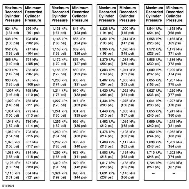
If one or more cylinders reads low, squirt approximately one tablespoon of engine oil meeting Ford specification on top of the pistons in the low-reading cylinders. Repeat the compression pressure check on these cylinders.

Compression Test - Interpreting Compression Readings

  1. If compression improves considerably, piston rings are worn or damaged.
  1. If compression does not improve, valves are sticking or not seating correctly.
  1. If 2 adjacent cylinders indicate low compression pressures and squirting oil on each piston does not increase compression, the head gasket may be leaking between cylinders. Engine oil or coolant in cylinders could result from this condition. Use the Compression Pressure Limit Chart when checking cylinder compression so the lowest reading is within 75% of the highest reading.

Cylinder Leakage Detection

When a cylinder produces a low reading, use of a cylinder leakage tester will be helpful in pinpointing the exact cause.

The leakage tester is inserted in the spark plug hole, the piston is brought up to TDC on the compression stroke, and compressed air is admitted.

Once the combustion chamber is pressurized, the leakage tester gauge will read the percentage of leakage. Leakage exceeding 20% is excessive.

While the air pressure is retained in the cylinder, listen for the hiss of escaping air. A leak at the intake valve will be heard in the Throttle Body (TB). A leak at the exhaust valve can be heard at the tailpipe. Leakage past the piston rings will be audible at the PCV connection. If air is passing through a blown head gasket to an adjacent cylinder, the noise will be evident at the spark plug hole of the cylinder into which the air is leaking. Cracks in the cylinder block or gasket leakage into the cooling system may be detected by a stream of bubbles in the radiator.

Excessive Engine Oil Consumption

Nearly all engines consume oil, which is essential for normal lubrication of the cylinder bore walls and pistons and rings. Determining the level of oil consumption may require testing by recording how much oil is being added over a given set of miles.

Customer driving habits greatly influence oil consumption. Mileage accumulated during towing or heavy loading generates extra heat. Frequent short trips, stop-and-go type traffic or extensive idling, prevent the engine from reaching normal operating temperature. This prevents component clearances from reaching specified operating ranges.

The following diagnostic procedure may be utilized to determine internal oil consumption. Make sure that the concern is related to internal oil consumption, and not external leakage, which also consumes oil. Verify there are no leaks before carrying out the test. Once verified, the rate of internal oil consumption can be tested.

A new engine may require extra oil in the early stages of operation. Internal piston-to-bore clearances and sealing characteristics improve as the engine breaks in. Engines are designed for close tolerances and do not require break-in oils or additives. Use the oil specified in the Owner's Literature. Ambient temperatures may determine the oil viscosity specification. Verify that the correct oil is being used for the vehicle in the geographic region in which it is driven.

Basic Pre-checks

  1. For persistent complaints of oil consumption, interview the customer to determine the oil consumption characteristics. If possible, determine the brand and grade of oil currently in the oil pan. Look at the oil filter or oil-change station tags to determine if Ford-recommended maintenance schedules have been followed. Make sure that the oil has been changed at the specified mileage intervals. If vehicle mileage is past the first recommended drain interval, the Original Equipment Manufacturer (OEM) production filter should have been changed.
  1. Ask how the most current mileage was accumulated. That is, determine whether the vehicle was driven under the following conditions:
  1. Verify that there are no external leaks. If necessary, review the diagnostic procedure under Engine Oil Leaks in the Diagnosis and Testing portion of this section.
  1. Inspect the crankcase ventilation system for:
  1. Inspect for signs of sludge. Sludge affects PCV performance and can plug or restrict cylinder head drainback wells. It can also increase oil pressure by restricting passages and reducing the drainback capability of piston oil control rings. Sludge can result from either excessive water ingestion in the crankcase or operation at extremely high crankcase temperatures.
  1. Inspect the air filter for dirt, sludge or damage. A hole in the filter element will allow unfiltered air to bypass into the air induction system. This can cause premature internal wear (engine dusting), allowing oil to escape past rings, pistons, valves and guides.
  1. If the engine is hot or was recently shut down, wait for a minimum 10-minutes to allow the oil to drain back. Ask the customer if this requirement has been followed. Adding oil without this wait period can cause an overfill condition, leading to excessive oil consumption and foaming which may cause engine damage.
  1. Make sure the oil level indicator (dipstick) is correctly and fully seated in the indicator tube. Remove the oil level indicator and record the oil level.

Detailed Pre-checks

  1. Check the thermostat opening temperature to make sure that the cooling system is operating at the specified temperature. If it is low, internal engine parts are not running at specified internal operating clearances.
  1. Verify the spark plugs are not oil saturated. Oil leaking into one or more cylinders will appear as an oil soaked condition on the plug. If a plug is saturated, a compression check may be necessary at the conclusion of the oil consumption test.

Oil Consumption Test

  1. NOTE: Once all of the previous conditions are met, carry out an oil consumption test.

    Drain the engine oil and remove the oil filter. Install a new manufacturer-specified oil filter. Make sure the vehicle is positioned on a level surface. Refill the oil pan to a level one liter (quart) less than the specified fill level, using manufacturer-specified oil.
  1. Run the engine for 3 minutes (if hot) or 10 minutes (if cold). Allow for a minimum 10-minute drainback period and then record the oil level shown on the oil level indicator. Place a mark on the backside of the oil level indicator noting the oil level location.
  1. Add the final one liter (quart) to complete the normal oil fill. Restart the engine and allow it to idle for 2 minutes. Shut the engine down.
  1. After a minimum 10-minute drainback period, record the location of the oil level again. Mark the oil level indicator with the new oil level location. (Note: Both marks should be very close to the MIN-MAX upper and lower limits or the upper and lower holes on the oil level indicator. These marks will exactly measure the engine's use of oil, with a one quart differential between the new marks.) Demonstrate to the customer that the factory-calibrated marks on the oil level indicator are where the oil should fall after an oil change with the specified fill amount. Explain however, that this may vary slightly between MIN-MAX or the upper and lower holes on the oil level indicator.
  1. Record the vehicle mileage.
  1. Advise the customer that oil level indicator readings must be taken every 320 km (200 mi) or weekly, using the revised marks as drawn. Remind the customer that the engine needs a minimum 10-minute drainback period for an accurate reading and that the oil level indicator must be firmly seated in the tube prior to taking the reading.
  1. When the subsequent indicator readings demonstrate a full liter (quart) has been used, record the vehicle mileage. The mileage driven should not be less than 4,800 km (3,000 mi). The drive cycle the vehicle has been operated under must be considered when making this calculation. It may be necessary to have the customer bring the vehicle in for a periodic oil level indicator reading to closely monitor oil usage.

Post Checks, Evaluation and Corrective Action

  1. If test results indicate excessive oil consumption, carry out a cylinder compression test. The cylinder compression test should be carried out with a fully charged battery and all spark plugs removed. See the Compression Test Chart in this section for pressure range limits.
  1. Compression should be consistent across all cylinders. Refer to the Compression Testing portion of this section. If compression tested within the specifications found in this section, the excessive oil consumption may be due to wear on the valve guides, valves or valve seals.
  1. A cylinder leak detection test can be carried out using a cylinder leakage detector. This can help identify valves, piston rings, or worn valve guides/valve stems, inoperative valve stem seals or other related areas as the source of oil consumption.
  1. NOTE: An oil-soaked appearance on the porcelain tips of the spark plugs also indicates excessive oil use. A typical engine with normal oil consumption will exhibit a light tan to brown appearance. A single or adjoining, multiple cylinder leak can be traced by viewing the tips.

    If an internal engine part is isolated as the root cause, determine if the repair will exceed cost limits and proceed with a repair strategy as required.
  1. Once corrective action to engine is complete and verifying that all pre-check items were eliminated in the original diagnosis, repeat the Oil Consumption Test as described above and verify consumption results.

Intake Manifold Vacuum Test

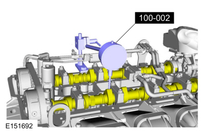
Bring the engine to normal operating temperature. Connect the Vacuum/Pressure Tester to the intake manifold. Run the engine at the specified idle speed.

The vacuum gauge should read between 51-74 kPa (15-22 in-Hg) depending upon the engine condition and the altitude at which the test is conducted. Subtract 4.0193 kPa (1 in-Hg) from the specified reading for every 304.8 m (1,000 feet) of elevation above sea level.

The reading should be steady. If necessary, adjust the gauge damper control (where used) if the needle is fluttering rapidly. Adjust the damper until the needle moves easily without excessive flutter.

Intake Manifold Vacuum Test - Interpreting Vacuum Gauge Readings

A careful study of the vacuum gauge reading while the engine is idling will help pinpoint trouble areas. Always conduct other appropriate tests before arriving at a final diagnostic decision. Vacuum gauge readings, although helpful, must be interpreted carefully.

Most vacuum gauges have a normal band indicated on the gauge face. The following are potential gauge readings. Some are normal; others should be investigated further.

The following are potential gauge readings. Some are normal; others should be investigated further.

  1. NORMAL READING: Needle between 51-74 kPa (15-22 in-Hg) and holding steady.
  1. NORMAL READING DURING RAPID ACCELERATION AND DECELERATION: When the engine is rapidly accelerated (dotted needle), the needle will drop to a low reading (not to zero). When the throttle is suddenly released, the needle will snap back up to a higher than normal figure.
  1. NORMAL FOR HIGH-LIFT CAMSHAFT WITH LARGE OVERLAP: The needle will register as low as 51 kPa (15 in-Hg) but will be relatively steady. Some oscillation is normal.
  1. WORN RINGS OR DILUTED OIL: When the engine is accelerated (dotted needle), the needle drops to 0 kPa (0 in-Hg). Upon deceleration, the needle runs slightly above 74 kPa (22 in-Hg).
  1. STICKING VALVES: When the needle (dotted) remains steady at a normal vacuum but occasionally flicks (sharp, fast movement) down and back about 13 kPa (4 in-Hg), one or more valves may be sticking.
  1. BURNED OR WARPED VALVES: A regular, evenly-spaced, downscale flicking of the needle indicates one or more burned or warped valves. Insufficient valve clearance will also cause this reaction.
  1. POOR VALVE SEATING: A small but regular downscale flicking can mean one or more valves are not seating.
  1. WORN VALVE GUIDES: When the needle oscillates over about a 13 kPa (4 in-Hg) range at idle speed, the valve guides could be worn. As engine speed increases, the needle will become steady if guides are responsible.
  1. WEAK VALVE SPRINGS: When the needle oscillation becomes more violent as engine rpm is increased, weak valve springs are indicated. The reading at idle could be relatively steady.
  1. LATE VALVE TIMING: A steady but low reading could be caused by late valve timing.
  1. IGNITION TIMING RETARDING: Retarded ignition timing will produce a steady but somewhat low reading.
  1. INSUFFICIENT SPARK PLUG GAP: When spark plugs are gapped too close, a regular, small pulsation of the needle can occur.
  1. INTAKE LEAK: A low, steady reading can be caused by an intake manifold or Throttle Body (TB) gasket leak.
  1. BLOWN HEAD GASKET: A regular drop of fair magnitude can be caused by a blown head gasket or warped cylinder head-to-cylinder block surface.
  1. RESTRICTED EXHAUST SYSTEM: When the engine is first started and is idled, the reading may be normal, but as the engine rpm is increased, the back pressure caused by a clogged muffler, kinked tailpipe or other concerns will cause the needle to slowly drop to 0 kPa (0 in-Hg). The needle then may slowly rise. Excessive exhaust clogging will cause the needle to drop to a low point even if the engine is only idling.

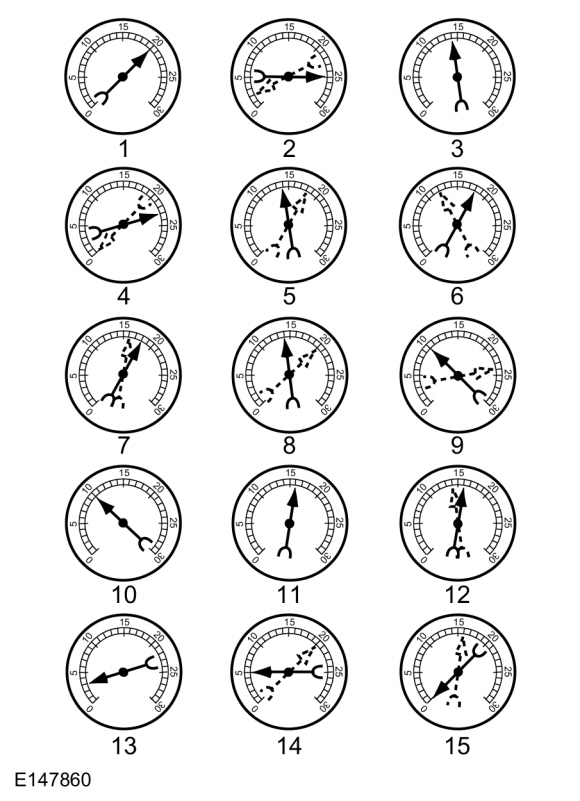
When vacuum leaks are indicated, search out and correct the cause. Excess air leaking into the system will upset the fuel mixture and cause concerns such as rough idle, missing on acceleration or burned valves. If the leak exists in an accessory unit such as the power brake booster, the unit will not function correctly. Always fix vacuum leaks.

Oil Pressure Test

  1. Disconnect and remove the EOP switch from the engine.
  1. Connect the EOP Gauge to the oil pressure sender oil galley port.
  1. Run the engine until normal operating temperature is reached.
  1. Run the engine at the specified rpm and record the gauge reading.
  1. The oil pressure should be within specifications, refer to the specification chart in the appropriate 303-01 engine section.
  1. If the pressure is not within specification, check the following possible sources:

Valve Train Analysis

The following component tests are used to diagnose valve train concerns.

Valve Train Analysis - Engine Off, Valve Cover Removed

Check for damaged or severely worn parts and correct assembly. Make sure correct parts are used with the static engine analysis as follows.

Valve Train Analysis - Camshafts and Valve Tappets

Valve Train Analysis - Valve Springs, Valve Tappets Removed

Valve Train Analysis - Valve Spring Retainer and Valve Spring Retainer Keys, Valve Tappets Removed

Valve Train Analysis - Valves and Cylinder Head, Valve Tappets Removed

Valve Train Analysis - Camshaft Lobe Lift

Check the lift of each camshaft lobe in consecutive order and make a note of the readings.

  1. Remove the spark plugs. Refer to the appropriate 303-07 section.
  1. Install the Dial Indicator Gauge with Holding Fixture so the rounded tip of the dial indicator is on top of the camshaft lobe and on the same plane as the valve tappet.
  1. Rotate the crankshaft using a breaker bar and socket attached to the crankshaft pulley retainer bolt. Rotate the crankshaft until the base circle of the camshaft lobe is reached.
  1. Zero the dial indicator. Continue to rotate the crankshaft until the high-lift point of the camshaft lobe is in the fully raised position (highest indicator reading).
  1. To check the accuracy of the original dial indicator reading, continue to rotate crankshaft until the base circle is reached. The indicator reading should be zero. If zero reading is not obtained, repeat Steps 2 through 5.
  1. If the lift on any lobe is below specified service limits, install a new camshaft and valve tappets.
  1. Install the spark plugs. Refer to the appropriate 303-07 section.