| 412-00 Climate Control System - General Information
|
2014 Fiesta
|
| Diagnosis and Testing
|
Procedure revision date:
05/16/2013
|
Climate Control System - Vehicles With: Electronic Automatic Temperature Control (EATC)
DTC Chart: Powertrain Control Module (PCM)
Diagnostics in this manual assume a certain skill level and knowledge of Ford-specific diagnostic practices. For information
about these practices,
REFER to:
Diagnostic Methods
(100-00 General Information, Description and Operation).
Network Diagnostic Trouble Codes (DTCs) (U-codes) are often a result of intermittent concerns such as damaged wiring or low
battery voltage occurrences. Additionally, vehicle repair procedures, such as module reprogramming, often set network Diagnostic
Trouble Codes (DTCs). Replacing a module to resolve a network
is unlikely to resolve the concern. To prevent repeat network
concerns, inspect all network wiring, especially connectors. Test the vehicle battery.
REFER to:
Battery
(414-01 Battery, Mounting and Cables, Diagnosis and Testing).
|
DTC
|
Description
|
Action
|
|
All Other
Diagnostic Trouble Codes (DTCs) not listed in this chart
|
—
|
-
For 1.6L EcoBoost,
REFER to:
Electronic Engine Controls
(303-14B Electronic Engine Controls - 1.6L EcoBoost (132kW/180PS) - Sigma, Diagnosis and Testing).
-
For 1.6L Duratec-16V Ti-VCT,
REFER to:
Electronic Engine Controls
(303-14A Electronic Engine Controls - 1.6L Duratec-16V Ti-VCT (88kW/120PS) - Sigma, Diagnosis and Testing).
|
|
P0532
|
A/C Refrigerant Pressure Sensor "A" Circuit Low
|
|
|
P0533
|
A/C Refrigerant Pressure Sensor "A" Circuit High
|
|
|
P0645
|
A/C Clutch Relay Control Circuit
|
|
|
P0646
|
A/C Clutch Relay Control Circuit Low
|
|
|
P0647
|
A/C Clutch Relay Control Circuit High
|
|
DTC Chart: Instrument Panel Cluster (IPC)
Diagnostics in this manual assume a certain skill level and knowledge of Ford-specific diagnostic practices. For information
about these practices,
REFER to:
Diagnostic Methods
(100-00 General Information, Description and Operation).
DTC Chart: Heating Ventilation Air Conditioning (HVAC) Control Module - Electronic Automatic Temperature Control (EATC)
Diagnostics in this manual assume a certain skill level and knowledge of Ford-specific diagnostic practices. For information
about these practices,
REFER to:
Diagnostic Methods
(100-00 General Information, Description and Operation).
Network Diagnostic Trouble Codes (DTCs) (U-codes) are often a result of intermittent concerns such as damaged wiring or low
battery voltage occurrences. Additionally, vehicle repair procedures, such as module reprogramming, often set network Diagnostic
Trouble Codes (DTCs). Replacing a module to resolve a network
is unlikely to resolve the concern. To prevent repeat network
concerns, inspect all network wiring, especially connectors. Test the vehicle battery.
REFER to:
Battery
(414-01 Battery, Mounting and Cables, Diagnosis and Testing).
|
DTC
|
Description
|
Action
|
|
B105A:11
|
Cabin Temperature Sensor Fan: Circuit Short To Ground
|
GO to Pinpoint Test O
|
|
B105A:15
|
Cabin Temperature Sensor Fan: Circuit Short To Battery or Open
|
GO to Pinpoint Test O
|
|
B1081:11
|
Left Temperature Damper Motor: Circuit Short To Ground
|
GO to Pinpoint Test K
|
|
B1081:12
|
Left Temperature Damper Motor: Circuit Short To Battery
|
GO to Pinpoint Test K
|
|
B1083:11
|
Recirculation Damper Motor: Circuit Short To Ground
|
GO to Pinpoint Test F
|
|
B1083:12
|
Recirculation Damper Motor: Circuit Short To Battery
|
GO to Pinpoint Test F
|
|
B1086:11
|
Air Distribution Damper Motor: Circuit Short To Ground
|
GO to Pinpoint Test R
|
|
B1086:12
|
Air Distribution Damper Motor: Circuit Short To Battery
|
GO to Pinpoint Test R
|
|
B10B5:11
|
Left Panel Air Discharge Temperature: Circuit Short To Ground
|
GO to Pinpoint Test Q
|
|
B10B5:15
|
Left Panel Air Discharge Temperature: Circuit Short To Battery or Open
|
GO to Pinpoint Test Q
|
|
B10B6:11
|
Left Floor Air Discharge Temperature: Circuit Short To Ground
|
GO to Pinpoint Test R
|
|
B10B6:15
|
Left Floor Air Discharge Temperature: Circuit Short To Battery or Open
|
GO to Pinpoint Test R
|
|
B10B8:97
|
Push Buttons: Component or System Operation Obstructed or Blocked
|
Buttons held too long may set this
. ATTEMPT to clean buttons. CLEAR the Diagnostic Trouble Codes (DTCs) and REPEAT the self-test. If the
does not return, IGNORE the
and CONTINUE diagnosing other Diagnostic Trouble Codes (DTCs) or symptoms. If the
returns, INSTALL a new
control module.
REFER to:
Heating, Ventilation and Air Conditioning (HVAC) Control Module
(412-00 Climate Control System - General Information, Removal and Installation).
|
|
B10B9:12
|
Blower Control: Circuit Short To Battery
|
GO to Pinpoint Test L
|
|
B10B9:14
|
Blower Control: Circuit Short To Ground or Open
|
GO to Pinpoint Test L
|
|
B1A59:11
|
Sensor 5 Volt Supply: Circuit Short To Ground
|
GO to Pinpoint Test S
|
|
B1A59:12
|
Sensor 5 Volt Supply: Circuit Short To Battery
|
GO to Pinpoint Test S
|
|
B1A61:11
|
Cabin Temperature Sensor: Circuit Short To Ground
|
GO to Pinpoint Test O
|
|
B1A61:15
|
Cabin Temperature Sensor: Circuit Short To Battery or Open
|
GO to Pinpoint Test O
|
|
B1A63:11
|
Right Solar Sensor: Circuit Short To Ground
|
GO to Pinpoint Test P
|
|
B1A63:15
|
Right Solar Sensor: Circuit Short To Battery or Open
|
GO to Pinpoint Test P
|
|
B1A64:11
|
Left Solar Sensor: Circuit Short To Ground
|
GO to Pinpoint Test P
|
|
B1A64:15
|
Left Solar Sensor: Circuit Short To Battery or Open
|
GO to Pinpoint Test P
|
|
U0140:00
|
Lost Communication With Body Control Module: No Sub Type Information
|
GO to Pinpoint Test T
|
|
U0155:00
|
Lost Communication With Instrument Panel Cluster (IPC) Control Module: No Sub Type Information
|
GO to Pinpoint Test U
|
|
U2100:00
|
Initial Configuration Not Complete: No Sub Type Information
|
CARRY OUT
on the
control module.
REFER to:
Module Configuration - System Operation and Component Description
(418-01 Module Configuration, Description and Operation).
REPEAT the self-test. If
is successful, the
will not be present. If the
returns, INSTALL a new
control module.
REFER to:
Heating, Ventilation and Air Conditioning (HVAC) Control Module
(412-00 Climate Control System - General Information, Removal and Installation).
|
|
U2101:00
|
Control Module Configuration Incompatible: No Sub Type Information
|
CHECK vehicle service history for recent service actions related to this module. This
sets due to incomplete or incorrect
procedures. If there have been recent service actions with this module, REPEAT or PERFORM the
procedure as directed by the scan tool.
REFER to:
Module Configuration - System Operation and Component Description
(418-01 Module Configuration, Description and Operation).
If there have been no recent service actions, INSTALL a new
control module to correct the failure to retain configuration data.
REFER to:
Heating, Ventilation and Air Conditioning (HVAC) Control Module
(412-00 Climate Control System - General Information, Removal and Installation).
|
|
U3000:00
|
Control Module: No Sub Type Information
|
INSTALL a new
control module.
REFER to:
Heating, Ventilation and Air Conditioning (HVAC) Control Module
(412-00 Climate Control System - General Information, Removal and Installation).
|
|
U3006:16
|
Control Module Input Power "A":Circuit Voltage Below Threshold
|
GO to Pinpoint Test V
|
|
U3006:17
|
Control Module Input Power "A":Circuit Voltage Above Threshold
|
GO to Pinpoint Test V
|
Symptom Chart(s)
Symptom Chart:
Diagnostics in this manual assume a certain skill level and knowledge of Ford-specific diagnostic practices. For information
about these practices,
REFER to:
Diagnostic Methods
(100-00 General Information, Description and Operation).
|
Condition
|
Possible Sources
|
Actions
|
|
Unable to duplicate the customer concern and no Diagnostic Trouble Codes (DTCs) present
|
Refer to Pinpoint Test
|
GO to Pinpoint Test E
|
|
Reduced outlet airflow
|
Refer to Pinpoint Test
|
|
|
The air inlet door is inoperative
|
Refer to Pinpoint Test
|
GO to Pinpoint Test F
|
|
Incorrect or erratic direction of airflow from outlets
|
Refer to Pinpoint Test
|
GO to Pinpoint Test G
|
|
Insufficient, erratic or no heat
|
Refer to Pinpoint Test
|
GO to Pinpoint Test H
|
|
The
is inoperative
|
Refer to Pinpoint Test
|
GO to Pinpoint Test I
|
|
Insufficient
cooling
|
Improper refrigerant level
|
|
|
Temperature door actuator
|
GO to Pinpoint Test K
|
|
The
is always on —
mode always commanded ON
|
Refer to Pinpoint Test
|
GO to Pinpoint Test J
|
|
Temperature control is inoperative or does not operate correctly
|
Refer to Pinpoint Test
|
GO to Pinpoint Test K
|
|
The blower motor is inoperative
|
Refer to Pinpoint Test
|
GO to Pinpoint Test L
|
|
The blower motor does not operate correctly
|
Refer to Pinpoint Test
|
GO to Pinpoint Test M
|
|
pressure relief valve discharging
|
High system pressure
|
|
|
pressure relief valve
|
Symptom Chart: Noise, Vibration, and Harshness (NVH)
Diagnostics in this manual assume a certain skill level and knowledge of Ford-specific diagnostic practices. For information
about these practices,
REFER to:
Diagnostic Methods
(100-00 General Information, Description and Operation).
|
Condition
|
Possible Sources
|
Actions
|
|
Noisy
compressor
|
compressor bearing worn
|
|
|
Excessive hissing from the plenum when the
is on
|
Low refrigerant charge
|
|
Pinpoint Test(s)
Diagnostics in this manual assume a certain skill level and knowledge of Ford-specific diagnostic practices. For information
about these practices,
REFER to:
Diagnostic Methods
(100-00 General Information, Description and Operation).
P0532, P0533 FOR 1.6L EcoBoost
Refer to Wiring Diagrams Cell 55 for schematic and connector information.
Normal Operation and Fault Conditions
The
pressure transducer receives a ground from the
. A 5-volt reference voltage is supplied to the
pressure transducer from the
. The
pressure transducer then sends a voltage to the
to indicate the
pressure.
Diagnostic Trouble Code (DTC) Fault Trigger Conditions
|
DTC
|
Description
|
Fault Trigger Conditions
|
|
P0532
|
A/C Refrigerant Pressure Sensor "A" Circuit Low
|
The
pressure transducer inputs a feedback voltage to the
. This
sets if the feedback voltage is less than 0.620 volt for at least 1 second and the ambient air temperature is greater than
0°C (32°F).
|
|
P0533
|
A/C Refrigerant Pressure Sensor "A" Circuit High
|
The
pressure transducer inputs a feedback voltage to the
. This
sets if the feedback voltage is greater than 4.90 volts for at least 1 second and the ambient air temperature is greater
than 0°C (32°F).
|
Possible Sources
-
Wiring, terminals or connectors
-
pressure transducer
-
Visual Inspection and Diagnostic Pre-checks
-
Inspect for loose or corroded
and
pressure transducer connections.
PINPOINT TEST A : P0532, P0533 FOR 1.6L ECOBOOST
| NOTICE:
Use the Rotunda Flex Probe kit when making measurements. Failure to use the correct probe adapter(s) may damage the connector.
|
| A1
COMPARE THE PCM (POWERTRAIN CONTROL MODULE)
A/C (AIR CONDITIONING)
PRESSURE SENSOR (ACP_PRESS) PID (PARAMETER IDENTIFICATION)
WITH THE MANIFOLD GAUGE SET READINGS
|
-
Allow the
system to stabilize to the outside ambient temperature.
-
Using a diagnostic scan tool, view
Parameter Identifications (PIDs).
-
With the manifold gauge set connected, compare the pressure readings of the manifold gauge set and the
ACP_PRESS
.
Are the pressure values of the manifold gauge set and the
ACP_PRESS
within +/-15 psi (103.4 kPa)?
| Yes
|
IGNORE the Diagnostic Trouble Codes (DTCs). REFER to the Symptom Chart in this section.
|
|
| A2
CHECK THE A/C (AIR CONDITIONING)
PRESSURE TRANSDUCER VREF CIRCUIT
|
-
Disconnect
Pressure Transducer C1260
.
-
Measure:
|
Positive Lead
|
Measurement / Action
|
Negative Lead
|
|
C1260-3
|

|
Ground
|
Is the voltage between 4.7 and 5.1 volts?
| No
|
If the voltage is less than 4.7 volts, GO to
A3
If the voltage is greater than 5.1 volts, REPAIR the circuit for a short to voltage.
|
|
| A3
CHECK THE A/C (AIR CONDITIONING)
PRESSURE TRANSDUCER VREF CIRCUIT FOR A SHORT TO GROUND
|
-
Measure:
|
Positive Lead
|
Measurement / Action
|
Negative Lead
|
|
C1260-3
|

|
Ground
|
Is the resistance greater than 10,000 ohms?
|
| A4
CHECK THE A/C (AIR CONDITIONING)
PRESSURE TRANSDUCER VREF CIRCUIT FOR AN OPEN
|
-
Measure:
|
Positive Lead
|
Measurement / Action
|
Negative Lead
|
|
C1260-3
|
|
C1915B-14
|
Is the resistance less than 3 ohms?
|
| A5
CHECK THE A/C (AIR CONDITIONING)
PRESSURE TRANSDUCER SIGNAL RETURN CIRCUIT
|
-
Measure:
|
Positive Lead
|
Measurement / Action
|
Negative Lead
|
|
C1260-1
|
|
C1260-3
|
Is the voltage greater than 4.7 volts?
| Yes
|
If diagnosing
P0532, GO to
A8
If diagnosing
P0533, GO to
A11
|
|
| A6
CHECK THE A/C (AIR CONDITIONING)
PRESSURE TRANSDUCER SIGNAL RETURN CIRCUIT FOR VOLTAGE
|
-
Measure:
|
Positive Lead
|
Measurement / Action
|
Negative Lead
|
|
C1260-1
|
|
Ground
|
Is any voltage present?
| Yes
|
If the voltage is less than 5.1 volts, REPAIR the signal return circuit for a short to the vref circuit. If the voltage is
greater than 5.1 volts, REPAIR the signal return circuit for a short to voltage.
|
|
| A7
CHECK THE A/C (AIR CONDITIONING)
PRESSURE TRANSDUCER SIGNAL RETURN CIRCUIT FOR AN OPEN
|
-
Measure:
|
Positive Lead
|
Measurement / Action
|
Negative Lead
|
|
C1260-1
|
|
C1915B-17
|
Is the resistance less than 3 ohms?
|
| A8
CHECK THE PCM (POWERTRAIN CONTROL MODULE)
A/C (AIR CONDITIONING)
PRESSURE SENSOR VOLTAGE (ACP_V) PID (PARAMETER IDENTIFICATION)
WITH THE A/C (AIR CONDITIONING)
PRESSURE TRANSDUCER SHORTED
|
-
Connect a fused jumper wire between:
|
Positive Lead
|
Measurement / Action
|
Negative Lead
|
|
C1260-2
|

|
C1260-3
|
-
Using a diagnostic scan tool, view
Parameter Identifications (PIDs).
Does the
voltage display between 4.7 and 5.1 volts?
| No
|
REMOVE the fused jumper wire. GO to
A9
|
|
| A9
CHECK THE A/C (AIR CONDITIONING)
PRESSURE TRANSDUCER FEEDBACK CIRCUIT FOR A SHORT TO THE SIGNAL RETURN CIRCUIT
|
-
Measure:
|
Positive Lead
|
Measurement / Action
|
Negative Lead
|
|
C1260-2
|
|
C1260-1
|
Is the resistance greater than 10,000 ohms?
|
| A10
CHECK THE A/C (AIR CONDITIONING)
PRESSURE TRANSDUCER FEEDBACK CIRCUIT FOR AN OPEN
|
-
Measure:
|
Positive Lead
|
Measurement / Action
|
Negative Lead
|
|
C1260-2
|
|
C1915B-52
|
Is the resistance less than 3 ohms?
|
| A11
CHECK THE PCM (POWERTRAIN CONTROL MODULE)
A/C (AIR CONDITIONING)
PRESSURE SENSOR VOLTAGE (ACP_V) PID (PARAMETER IDENTIFICATION)
|
-
Using a diagnostic scan tool, view
Parameter Identifications (PIDs).
Does the
voltage display 0 volts?
|
| A12
CHECK THE A/C (AIR CONDITIONING)
PRESSURE TRANSDUCER FEEDBACK CIRCUIT FOR VOLTAGE
|
-
Measure:
|
Positive Lead
|
Measurement / Action
|
Negative Lead
|
|
C1260-2
|
|
Ground
|
Is any voltage present?
|
| A13
CHECK THE A/C (AIR CONDITIONING)
PRESSURE TRANSDUCER FEEDBACK CIRCUIT FOR A SHORT TO VOLTAGE
|
-
Measure:
|
Positive Lead
|
Measurement / Action
|
Negative Lead
|
|
C1260-2
|
|
Ground
|
Is any voltage present?
| No
|
REPAIR the vref circuit for a short to the feedback circuit.
|
|
| A14
CHECK FOR CORRECT PCM (POWERTRAIN CONTROL MODULE)
OPERATION
|
-
Disconnect and inspect all
connectors.
-
Repair:
-
corrosion (install new connector or terminals – clean module pins)
-
damaged or bent pins – install new terminals/pins
-
pushed-out pins – install new pins as necessary
-
Connect the
connectors. Make sure they seat and latch correctly.
-
Operate the system and determine if the concern is still present.
Is the concern still present?
| Yes
|
CHECK
for any applicable Technical Service Bulletins (TSBs). If a
exists for this concern, DISCONTINUE this test and FOLLOW
instructions. If no Technical Service Bulletins (TSBs) address this concern, INSTALL a new
.
REFER to:
Powertrain Control Module (PCM)
(303-14B Electronic Engine Controls - 1.6L EcoBoost (132kW/180PS) - Sigma, Removal and Installation).
|
| No
|
The system is operating correctly at this time. The concern may have been caused by a loose or corroded connector. ADDRESS
the root cause of any connector or pin issues.
|
|
P0532, P0533 For 1.6L Duratec-16V Ti-VCT
Refer to Wiring Diagrams Cell 55 for schematic and connector information.
Normal Operation and Fault Conditions
The
pressure transducer receives a ground from the
. A 5-volt reference voltage is supplied to the
pressure transducer from the
. The
pressure transducer then sends a voltage to the
to indicate the
pressure.
Diagnostic Trouble Code (DTC) Fault Trigger Conditions
|
DTC
|
Description
|
Fault Trigger Conditions
|
|
P0532
|
A/C Refrigerant Pressure Sensor "A" Circuit Low
|
The
pressure transducer inputs a feedback voltage to the
. This
sets if the feedback voltage is less than 0.620 volt for at least 1 second and the ambient air temperature is greater than
0°C (32°F).
|
|
P0533
|
A/C Refrigerant Pressure Sensor "A" Circuit High
|
The
pressure transducer inputs a feedback voltage to the
. This
sets if the feedback voltage is greater than 4.90 volts for at least 1 second and the ambient air temperature is greater
than 0°C (32°F).
|
Possible Sources
-
Wiring, terminals or connectors
-
pressure transducer
-
Visual Inspection and Diagnostic Pre-checks
-
Inspect for loose or corroded
and
pressure transducer connections.
PINPOINT TEST B : P0532, P0533 FOR 1.6L DURATEC-16V TI-VCT
| NOTICE:
Use the Rotunda Flex Probe kit when making measurements. Failure to use the correct probe adapter(s) may damage the connector.
|
| B1
COMPARE THE PCM (POWERTRAIN CONTROL MODULE)
A/C (AIR CONDITIONING)
PRESSURE SENSOR (ACP_PRESS) PID (PARAMETER IDENTIFICATION)
WITH THE MANIFOLD GAUGE SET READINGS
|
-
Allow the
system to stabilize to the outside ambient temperature.
-
Using a diagnostic scan tool, view
Parameter Identifications (PIDs).
-
With the manifold gauge set connected, compare the pressure readings of the manifold gauge set and the
ACP_PRESS
.
Are the pressure values of the manifold gauge set and the
within +/-15 psi (103.4 kPa)?
| Yes
|
IGNORE the Diagnostic Trouble Codes (DTCs). REFER to the Symptom Chart in this section.
|
|
| B2
CHECK THE A/C (AIR CONDITIONING)
PRESSURE TRANSDUCER VREF CIRCUIT
|
-
Disconnect
Pressure Transducer C1260
.
-
Measure:
|
Positive Lead
|
Measurement / Action
|
Negative Lead
|
|
C1260-3
|
|
Ground
|
Is the voltage between 4.7 and 5.1 volts?
| No
|
If the voltage is less than 4.7 volts, GO to
B3
If the voltage is greater than 5.1 volts, REPAIR the circuit for a short to voltage.
|
|
| B3
CHECK THE A/C (AIR CONDITIONING)
PRESSURE TRANSDUCER VREF CIRCUIT FOR A SHORT TO GROUND
|
-
Measure:
|
Positive Lead
|
Measurement / Action
|
Negative Lead
|
|
C1260-3
|
|
Ground
|
Is the resistance greater than 10,000 ohms?
|
| B4
CHECK THE A/C (AIR CONDITIONING)
PRESSURE TRANSDUCER VREF CIRCUIT FOR AN OPEN
|
-
Measure:
|
Positive Lead
|
Measurement / Action
|
Negative Lead
|
|
C1260-3
|
|
C175B-16
|
Is the resistance less than 3 ohms?
|
| B5
CHECK THE A/C (AIR CONDITIONING)
PRESSURE TRANSDUCER SIGNAL RETURN CIRCUIT
|
-
Measure:
|
Positive Lead
|
Measurement / Action
|
Negative Lead
|
|
C1260-1
|
|
C1260-3
|
Is the voltage greater than 4.7 volts?
| Yes
|
If diagnosing
P0532, GO to
B8
If diagnosing
P0533, GO to
B11
|
|
| B6
CHECK THE A/C (AIR CONDITIONING)
PRESSURE TRANSDUCER SIGNAL RETURN CIRCUIT FOR VOLTAGE
|
-
Measure:
|
Positive Lead
|
Measurement / Action
|
Negative Lead
|
|
C1260-1
|
|
Ground
|
Is any voltage present?
| Yes
|
If the voltage is less than 5.1 volts, REPAIR the signal return circuit for a short to the vref circuit. If the voltage is
greater than 5.1 volts, REPAIR the signal return circuit for a short to voltage.
|
|
| B7
CHECK THE A/C (AIR CONDITIONING)
PRESSURE TRANSDUCER SIGNAL RETURN CIRCUIT FOR AN OPEN
|
-
Measure:
|
Positive Lead
|
Measurement / Action
|
Negative Lead
|
|
C1260-1
|
|
C175B-40
|
Is the resistance less than 3 ohms?
|
| B8
CHECK THE PCM (POWERTRAIN CONTROL MODULE)
A/C (AIR CONDITIONING)
PRESSURE SENSOR VOLTAGE (ACP_V) PID (PARAMETER IDENTIFICATION)
WITH THE A/C (AIR CONDITIONING)
PRESSURE TRANSDUCER SHORTED
|
-
Connect a fused jumper wire between:
|
Positive Lead
|
Measurement / Action
|
Negative Lead
|
|
C1260-2
|
|
C1260-3
|
-
Using a diagnostic scan tool, view
Parameter Identifications (PIDs).
Does the
voltage read between 4.7 and 5.1 volts?
| No
|
REMOVE the fused jumper wire. GO to
B9
|
|
| B9
CHECK THE A/C (AIR CONDITIONING)
PRESSURE TRANSDUCER FEEDBACK CIRCUIT FOR A SHORT TO THE SIGNAL RETURN CIRCUIT
|
-
Measure:
|
Positive Lead
|
Measurement / Action
|
Negative Lead
|
|
C1260-2
|
|
C1260-1
|
Is the resistance greater than 10,000 ohms?
|
| B10
CHECK THE A/C (AIR CONDITIONING)
PRESSURE TRANSDUCER FEEDBACK CIRCUIT FOR AN OPEN
|
-
Measure:
|
Positive Lead
|
Measurement / Action
|
Negative Lead
|
|
C1260-2
|
|
C175B-28
|
Is the resistance less than 3 ohms?
|
| B11
CHECK THE PCM (POWERTRAIN CONTROL MODULE)
A/C (AIR CONDITIONING)
PRESSURE SENSOR VOLTAGE (ACP_V) PID (PARAMETER IDENTIFICATION)
|
-
Using a diagnostic scan tool, view
Parameter Identifications (PIDs).
Does the
voltage display 0 volts?
|
| B12
CHECK THE A/C (AIR CONDITIONING)
PRESSURE TRANSDUCER FEEDBACK CIRCUIT FOR VOLTAGE
|
-
Measure:
|
Positive Lead
|
Measurement / Action
|
Negative Lead
|
|
C1260-2
|
|
Ground
|
Is any voltage present?
|
| B13
CHECK THE A/C (AIR CONDITIONING)
PRESSURE TRANSDUCER FEEDBACK CIRCUIT FOR A SHORT TO VOLTAGE
|
-
Measure:
|
Positive Lead
|
Measurement / Action
|
Negative Lead
|
|
C1260-2
|
|
Ground
|
Is any voltage present?
| No
|
REPAIR the vref circuit for a short to the feedback circuit.
|
|
| B14
CHECK FOR CORRECT PCM (POWERTRAIN CONTROL MODULE)
OPERATION
|
-
Disconnect and inspect all
connectors.
-
Repair:
-
corrosion (install new connector or terminals – clean module pins)
-
damaged or bent pins – install new terminals/pins
-
pushed-out pins – install new pins as necessary
-
Connect the
connectors. Make sure they seat and latch correctly.
-
Operate the system and determine if the concern is still present.
Is the concern still present?
| Yes
|
CHECK
for any applicable Technical Service Bulletins (TSBs). If a
exists for this concern, DISCONTINUE this test and FOLLOW
instructions. If no Technical Service Bulletins (TSBs) address this concern, INSTALL a new
.
REFER to:
Powertrain Control Module (PCM)
(303-14A Electronic Engine Controls - 1.6L Duratec-16V Ti-VCT (88kW/120PS) - Sigma, Removal and Installation).
|
| No
|
The system is operating correctly at this time. The concern may have been caused by a loose or corroded connector. ADDRESS
the root cause of any connector or pin issues.
|
|
P0645, P0646, P0647 For 1.6L EcoBoost
Refer to Wiring Diagrams Cell 55 for schematic and connector information.
Normal Operation and Fault Conditions
Voltage is provided to the
clutch relay coil. When
is requested and
line pressures allow, a ground is provided to the
clutch relay coil from the
, energizing the
clutch relay.
Diagnostic Trouble Code (DTC) Fault Trigger Conditions
|
DTC
|
Description
|
Fault Trigger Conditions
|
|
P0645
|
A/C Clutch Relay Control Circuit
|
This
sets when the
grounds the relay circuit and more voltage than expected is detected on the relay circuit. This
also sets when the relay circuit is OFF and no voltage is detected on the relay circuit. The
expects to detect voltage coming through the relay coil to the relay circuit when it is not grounding it.
|
|
P0646
|
A/C Clutch Relay Control Circuit Low
|
This
sets when the relay circuit is OFF and ground is detected on the relay circuit.
|
|
P0647
|
A/C Clutch Relay Control Circuit High
|
This
sets when the
grounds the relay circuit and excessive current draw (short to voltage) is detected on the relay circuit while
is ON.
|
Possible Sources
-
Wiring, terminals or connectors
-
clutch relay
-
Visual Inspection and Diagnostic Pre-checks
-
Inspect
fuse 24 (10A).
-
Inspect
fuse 30 (10A).
-
Inspect the
clutch relay for looseness or corrosion.
P0645, P0646, P0647 For 1.6L Duratec-16V Ti-VCT
Refer to Wiring Diagrams Cell 55 for schematic and connector information.
Normal Operation and Fault Conditions
Voltage is provided to the
clutch relay coil. When
is requested and
line pressures allow, a ground is provided to the
clutch relay coil from the
, energizing the
clutch relay.
Diagnostic Trouble Code (DTC) Fault Trigger Conditions
|
DTC
|
Description
|
Fault Trigger Conditions
|
|
P0645
|
A/C Clutch Relay Control Circuit
|
This
sets when the
grounds the relay circuit and more voltage than expected is detected on the relay circuit. This
also sets when the relay circuit is OFF and no voltage is detected on the relay circuit. The
expects to detect voltage coming through the relay coil to the relay circuit when it is not grounding it.
|
|
P0646
|
A/C Clutch Relay Control Circuit Low
|
This
sets when the relay circuit is OFF and ground is detected on the relay circuit.
|
|
P0647
|
A/C Clutch Relay Control Circuit High
|
This
sets when the
grounds the relay circuit and excessive current draw (short to voltage) is detected on the relay circuit while
is ON.
|
Possible Sources
-
Wiring, terminals or connectors
-
clutch relay
-
Visual Inspection and Diagnostic Pre-checks
-
Inspect
fuse 24 (10A).
-
Inspect
fuse 30 (10A).
-
Inspect the
clutch relay for looseness or corrosion.
Unable To Duplicate The Customer Concern And No Diagnostic Trouble Codes (DTCs) Present
This pinpoint test tests the functions of the
system and identifies the correct
symptom pinpoint test.
PINPOINT TEST E : UNABLE TO DUPLICATE THE CUSTOMER CONCERN AND NO DIAGNOSTIC TROUBLE CODES (DTCS) PRESENT
| E1
CHECK THE BLOWER MOTOR OPERATION
|
-
Observe blower motor operation and select each blower motor speed.
Does the blower motor operate in all selections and change speed in each?
|
| E2
CHECK AIRFLOW OPERATION
|
-
Select the highest blower motor setting.
-
While observing the airflow, select each of the airflow positions (PANEL, PANEL/FLOOR, FLOOR, FLOOR/DEFROST, DEFROST).
Is the airflow directed to the correct outlets?
|
| E3
VERIFY TEMPERATURE CONTROL OPERATION
|
-
Start the vehicle and allow it to reach normal operating temperature.
-
With the
off, select PANEL mode.
-
Change the temperature setting from the coldest to the warmest and back to the coldest.
Does the temperature change between very warm to cool?
|
| E4
VERIFY THE A/C (AIR CONDITIONING)
CLUTCH DOES NOT ENGAGE WITH A/C (AIR CONDITIONING)
OFF
|
-
With the engine running and the
off, select PANEL mode.
-
Select the coldest temperature setting.
Is the outlet temperature close to ambient temperature?
| No
|
If the temperature is warmer than ambient temperature,
GO to Pinpoint Test I
If the outlet temperature is significantly colder than ambient temperature and the
compressor clutch engages,
GO to Pinpoint Test J
|
|
| E5
VERIFY A/C (AIR CONDITIONING)
CLUTCH ENGAGEMENT IN THE A/C (AIR CONDITIONING)
MODE
|
-
Make sure the ambient air temperature is above 2°C (36°F).
-
With the engine running, select PANEL mode.
-
Press the
button (indicator on).
Does the
clutch engage when in PANEL mode and the
button (indicator on) is pressed?
|
| E6
CHECK THE RECIRC OPERATION
|
-
With the engine running, press the RECIRC button (indicator off).
-
Select the highest blower motor setting.
-
Press the RECIRC button (indicator on).
Does the airflow noise increase when the RECIRC mode is selected (indicator on)?
| Yes
|
The system is operating normally.
|
|
The Air Inlet Door Is Inoperative
Refer to Wiring Diagrams Cell 55 for schematic and connector information.
Normal Operation and Fault Conditions
Air Inlet Door Actuator,
REFER to:
Climate Control System - Vehicles With: Electronic Automatic Temperature Control (EATC) - System Operation and Component Description
(412-00 Climate Control System - General Information, Description and Operation).
Diagnostic Trouble Code (DTC) Fault Trigger Conditions
|
DTC
|
Description
|
Fault Trigger Conditions
|
|
B1083:11
|
Recirculation Damper Motor: Circuit Short To Ground
|
The
control module senses lower than expected voltage on the motor circuits, indicating a short to ground.
|
|
B1083:12
|
Recirculation Damper Motor: Circuit Short To Battery
|
The
control module senses greater than expected voltage on the motor circuits, indicating a short to voltage.
|
Possible Sources
-
Wiring, terminals or connectors
-
Air inlet door actuator
-
control module
Visual Inspection and Diagnostic Pre-checks
PINPOINT TEST F : THE AIR INLET DOOR IS INOPERATIVE
| NOTICE:
Use the Rotunda Flex Probe kit when making measurements. Failure to use the correct probe adapter(s) may damage the connector.
|
| F1
CHECK THE AIR INLET DOOR ACTUATOR MOTOR CIRCUITS FOR A SHORT TO VOLTAGE
|
-
Disconnect Air Inlet Door Actuator C2091
.
-
Disconnect
control module C228A
.
-
Measure:
|
Positive Lead
|
Measurement / Action
|
Negative Lead
|
|
C2091-1
|
|
Ground
|
|
C2091-6
|
|
Ground
|
Is any voltage present?
| Yes
|
REPAIR the affected circuits.
|
|
| F2
CHECK THE AIR INLET DOOR ACTUATOR MOTOR CIRCUITS FOR A SHORT TO GROUND
|
-
Measure:
|
Positive Lead
|
Measurement / Action
|
Negative Lead
|
|
C2091-1
|
|
Ground
|
|
C2091-6
|
|
Ground
|
Are the resistances greater than 10,000 ohms?
| No
|
REPAIR the affected circuits.
|
|
| F3
CHECK THE AIR INLET DOOR ACTUATOR MOTOR CIRCUITS FOR AN OPEN
|
-
Measure:
|
Positive Lead
|
Measurement / Action
|
Negative Lead
|
|
C2091-1
|
|
C228A-7
|
|
C2091-6
|
|
C228A-8
|
Are the resistances less than 3 ohms?
| No
|
REPAIR the affected circuits.
|
|
| F4
CHECK THE AIR INLET DOOR ACTUATOR MOTOR CIRCUITS FOR A SHORT TOGETHER
|
-
Measure:
|
Positive Lead
|
Measurement / Action
|
Negative Lead
|
|
C2091-1
|
|
C2091-6
|
Is the resistance greater than 10,000 ohms?
| Yes
|
INSTALL a new air inlet door actuator.
REFER to:
Air Inlet Door Actuator
(412-00 Climate Control System - General Information, Removal and Installation).
TEST the system for normal operation. If the concern is still present, GO to
F5
|
|
| F5
CHECK FOR CORRECT HVAC (HEATING, VENTILATION AND AIR CONDITIONING)
CONTROL MODULE OPERATION
|
-
Disconnect and inspect all
control module connectors.
-
Repair:
-
corrosion (install new connector or terminals – clean module pins)
-
damaged or bent pins – install new terminals/pins
-
pushed-out pins – install new pins as necessary
-
Connect the
control module connectors. Make sure they seat and latch correctly.
-
Operate the system and determine if the concern is still present.
Is the concern still present?
| Yes
|
CHECK
for any applicable Technical Service Bulletins (TSBs). If a
exists for this concern, DISCONTINUE this test and FOLLOW
instructions. If no Technical Service Bulletins (TSBs) address this concern, INSTALL a new
control module.
REFER to:
Heating, Ventilation and Air Conditioning (HVAC) Control Module
(412-00 Climate Control System - General Information, Removal and Installation).
|
| No
|
The system is operating correctly at this time. The concern may have been caused by a loose or corroded connector. ADDRESS
the root cause of any connector or pin issues.
|
|
Incorrect Or Erratic Direction Of Airflow From Outlets
Refer to Wiring Diagrams Cell 55 for schematic and connector information.
Normal Operation and Fault Conditions
Air distribution door actuator,
REFER to:
Climate Control System - Vehicles With: Electronic Automatic Temperature Control (EATC) - System Operation and Component Description
(412-00 Climate Control System - General Information, Description and Operation).
Diagnostic Trouble Code (DTC) Fault Trigger Conditions
|
DTC
|
Description
|
Fault Trigger Conditions
|
|
B1086:11
|
Air Distribution Damper Motor: Circuit Short To Ground
|
The
control module senses lower than expected voltage on the motor circuits, indicating a short to ground.
|
|
B1086:12
|
Air Distribution Damper Motor: Circuit Short To Battery
|
The
control module senses greater than expected voltage on the motor circuits, indicating a short to voltage.
|
Possible Sources
-
Wiring, terminals or connectors
-
Air distribution door actuator
-
control module
Visual Inspection and Diagnostic Pre-checks
PINPOINT TEST G : INCORRECT OR ERRATIC DIRECTION OF AIRFLOW FROM OUTLETS
| NOTICE:
Use the Rotunda Flex Probe kit when making measurements. Failure to use the correct probe adapter(s) may damage the connector.
|
| G1
CHECK THE AIR DISTRIBUTION DOOR ACTUATOR CIRCUITS FOR A SHORT TO VOLTAGE
|
-
Disconnect
control module C228A
.
-
Disconnect Air Distribution Door Actuator C236
.
-
Disconnect Temperature Door Actuator C2092
.
-
Measure:
|
Positive Lead
|
Measurement / Action
|
Negative Lead
|
|
C236-1
|
|
Ground
|
|
C236-2
|
|
Ground
|
|
C236-3
|
|
Ground
|
|
C236-4
|
|
Ground
|
|
C236-6
|
|
Ground
|
Is there any voltage present?
| Yes
|
REPAIR the circuit in question.
|
|
| G2
CHECK THE AIR DISTRIBUTION DOOR ACTUATOR CIRCUITS FOR A SHORT TO GROUND
|
-
Measure:
|
Positive Lead
|
Measurement / Action
|
Negative Lead
|
|
C236-1
|
|
Ground
|
|
C236-2
|
|
Ground
|
|
C236-3
|
|
Ground
|
|
C236-4
|
|
Ground
|
|
C236-6
|
|
Ground
|
Are the resistances greater than 10,000 ohms?
| No
|
REPAIR the circuit in question.
|
|
| G3
CHECK THE AIR DISTRIBUTION DOOR ACTUATOR CIRCUITS FOR AN OPEN
|
-
Measure:
|
Positive Lead
|
Measurement / Action
|
Negative Lead
|
|
C236-1
|
|
C228A-9
|
|
C236-2
|
|
C228A-12
|
|
C236-3
|
|
C228A-13
|
|
C236-4
|
|
C228A-15
|
|
C236-6
|
|
C228A-4
|
Are the resistances less than 3 ohms?
| Yes
|
INSTALL a new air distribution door actuator.
REFER to:
Air Distribution Door Actuator
(412-00 Climate Control System - General Information, Removal and Installation).
Operate the system and determine if the concern is still present. If the concern is still present, GO to
G4
|
| No
|
REPAIR the circuit in question.
|
|
| G4
CHECK FOR CORRECT HVAC (HEATING, VENTILATION AND AIR CONDITIONING)
CONTROL MODULE OPERATION
|
-
Disconnect and inspect all
control module connectors.
-
Repair:
-
corrosion (install new connector or terminals – clean module pins)
-
damaged or bent pins – install new terminals/pins
-
pushed-out pins – install new pins as necessary
-
Connect the
control module connectors. Make sure they seat and latch correctly.
-
Operate the system and determine if the concern is still present.
Is the concern still present?
| Yes
|
CHECK
for any applicable Technical Service Bulletins (TSBs). If a
exists for this concern, DISCONTINUE this test and FOLLOW
instructions. If no Technical Service Bulletins (TSBs) address this concern, INSTALL a new
control module.
REFER to:
Heating, Ventilation and Air Conditioning (HVAC) Control Module
(412-00 Climate Control System - General Information, Removal and Installation).
|
| No
|
The system is operating correctly at this time. The concern may have been caused by a loose or corroded connector. ADDRESS
the root cause of any connector or pin issues.
|
|
Insufficient, Erratic Or No Heat
Refer to Wiring Diagrams Cell 55 for schematic and connector information.
Normal Operation and Fault Conditions
When the engine is at operating temperature hot coolant flows from the engine through the heater core and back to the engine.
Correct coolant temperatures are critical for good heater performance.
Possible Sources
-
Low engine coolant level
-
Plugged or partially plugged heater core
-
Temperature binding or stuck
-
Temperature door actuator
Visual Inspection and Diagnostic Pre-checks
-
Inspect for low engine coolant level.
PINPOINT TEST H : INSUFFICIENT, ERRATIC OR NO HEAT
| H1
CHECK FOR CORRECT ENGINE COOLANT LEVEL
|
-
Check the engine coolant level.
Is the engine coolant at the correct level (hot/cold) as indicated on the engine coolant recovery reservoir?
| No
|
For 1.6L EcoBoost,
REFER to:
Engine Cooling
(303-03B Engine Cooling - 1.6L EcoBoost (132kW/180PS) - Sigma, Diagnosis and Testing).
For 1.6L Duratec-16V Ti-VCT,
REFER to:
Engine Cooling
(303-03A Engine Cooling - 1.6L Duratec-16V Ti-VCT (88kW/120PS) - Sigma, Diagnosis and Testing).
|
|
| H2
CHECK FOR COOLANT FLOW TO THE HEATER CORE
|
-
Run the motor until it reaches normal operating temperature. Select the floor position on the control assembly. Set the temperature
control to full warm and the blower to the lowest setting.
-
Using a suitable temperature measuring device, check the heater core inlet hose to see if it is hot.
Is the heater core inlet hose hot?
| No
|
For 1.6L EcoBoost,
REFER to:
Engine Cooling
(303-03B Engine Cooling - 1.6L EcoBoost (132kW/180PS) - Sigma, Diagnosis and Testing).
For 1.6L Duratec-16V Ti-VCT,
REFER to:
Engine Cooling
(303-03A Engine Cooling - 1.6L Duratec-16V Ti-VCT (88kW/120PS) - Sigma, Diagnosis and Testing).
|
|
| H3
CHECK FOR A PLUGGED OR RESTRICTED HEATER CORE
|
-
Using a suitable temperature measuring device, measure the heater core outlet hose temperature.
Is the heater core outlet hose temperature similar to the inlet hose temperature (within approximately 6-17°C [10-30°F])?
| No
|
INSTALL a new heater core.
REFER to:
Heater Core
(412-00 Climate Control System - General Information, Removal and Installation).
|
|
The
Is Inoperative
Refer to Wiring Diagrams Cell 55 for schematic and connector information.
Normal Operation and Fault Conditions
Control System Logic,
REFER to:
Climate Control System - Vehicles With: Electronic Automatic Temperature Control (EATC) - System Operation and Component Description
(412-00 Climate Control System - General Information, Description and Operation).
Possible Sources
-
Wiring, terminals or connectors
-
pressure transducer
-
-
control module
-
-
Evaporator temperature sensor
Visual Inspection and Diagnostic Pre-checks
-
Inspect
fuse 12 (7.5A).
-
Inspect
fuse 21 (7.5A).
-
Inspect
fuse 24 (10A).
-
Inspect
fuse 30 (10A).
-
Inspect the
clutch relay.
PINPOINT TEST I : THE A/C (AIR CONDITIONING)
IS INOPERATIVE
| NOTICE:
Use the Rotunda Flex Probe kit when making measurements. Failure to use the correct probe adapter(s) may damage the connector.
|
| I1
CLEAR AND RETRIEVE DIAGNOSTIC TROUBLE CODES (DTCS)
|
-
Using a diagnostic scan tool, clear all Diagnostic Trouble Codes (DTCs).
-
Using a diagnostic scan tool, retrieve all Continuous Memory Diagnostic Trouble Codes (CMDTCs).
Are there any climate control related Diagnostic Trouble Codes (DTCs)?
| Yes
|
REFER to
charts in this section.
|
|
| I2
CHECK THE OUTSIDE AIR TEMPERATURE DISPLAY IN THE IPC (INSTRUMENT PANEL CLUSTER)
|
-
Observe the outside air temperature display in the
.
Is the outside air temperature display similar to the ambient temperature?
|
| I3
CHECK THE A/C (AIR CONDITIONING)
SYSTEM PRESSURE
|
-
With the R-134a manifold gauge set connected, check the
system pressure.
Is the
system pressure above 290 kPa (42 psi)?
|
| I4
CHECK THE PCM (POWERTRAIN CONTROL MODULE)
A/C (AIR CONDITIONING)
PRESSURE SENSOR (ACP_PRESS) PID (PARAMETER IDENTIFICATION)
|
-
Using a diagnostic scan tool, view
Parameter Identifications (PIDs).
-
With the R-134a manifold gauge set connected, compare the pressure readings of the manifold gauge set and the
ACP_PRESS
.
Are the pressure values of the manifold gauge set and the
ACP_PRESS
similar?
|
| I5
CHECK THE IPC (INSTRUMENT PANEL CLUSTER)
A/C (AIR CONDITIONING)
EVAPORATOR TEMPERATURE (EVAP_TEMP) PID (PARAMETER IDENTIFICATION)
|
-
Allow the vehicle exterior and interior to stabilize to the ambient temperature.
-
Using a diagnostic scan tool, view
Parameter Identifications (PIDs).
Does the
display similar to the ambient temperature?
|
| I6
CHECK THE HVAC (HEATING, VENTILATION AND AIR CONDITIONING)
CONTROL MODULE A/C (AIR CONDITIONING)
SWITCH (A/C_SWITCH) PID (PARAMETER IDENTIFICATION)
WITH THE A/C (AIR CONDITIONING)
ON
|
-
Using a diagnostic scan tool, view
Parameter Identifications (PIDs).
-
Monitor the
control module A/C_SWITCH
.
-
Select PANEL and press the
button (indicator on) on the
controls.
Does the
control module A/C_SWITCH
display Active?
|
| I7
CHECK THE PCM (POWERTRAIN CONTROL MODULE)
A/C (AIR CONDITIONING)
REQUEST SIGNAL (AC_REQ) PID (PARAMETER IDENTIFICATION)
WITH THE A/C (AIR CONDITIONING)
ON
|
-
Using a diagnostic scan tool, view
Parameter Identifications (PIDs).
-
Select PANEL and press the
button (indicator on) on the
controls.
Does the
AC_REQ
display Yes?
|
| I8
CHECK THE PCM (POWERTRAIN CONTROL MODULE)
A/C (AIR CONDITIONING)
COMPRESSOR COMMANDED STATE (ACC_CMD) PID (PARAMETER IDENTIFICATION)
WITH THE A/C (AIR CONDITIONING)
ON
|
-
Using a diagnostic scan tool, view
Parameter Identifications (PIDs).
-
Select PANEL and press the
button (indicator on) on the
controls.
Does the
ACC_CMD
display ON?
|
| I9
CHECK THE VOLTAGE AT THE A/C (AIR CONDITIONING)
COMPRESSOR CLUTCH FIELD COIL
|
-
Disconnect
Compressor Clutch Field Coil C100
.
-
Select MAX A/C on the
controls.
-
Measure:
|
Positive Lead
|
Measurement / Action
|
Negative Lead
|
|
C100-1
|
|
Ground
|
Is the voltage greater than 11 volts?
|
| I10
CHECK THE GROUND AT THE A/C (AIR CONDITIONING)
COMPRESSOR CLUTCH FIELD COIL
|
-
Measure:
|
Positive Lead
|
Measurement / Action
|
Negative Lead
|
|
C100-2
|
|
Ground
|
Is the resistance less than 3 ohms?
|
| I11
CHECK THE A/C (AIR CONDITIONING)
COMPRESSOR CLUTCH FIELD COIL
|
-
Measure:
|
Positive Lead
|
Measurement / Action
|
Negative Lead
|
 C100-1 (component side)
|
|
C100-2 (component side)
|
Is the resistance between 2 and 5 ohms?
|
| I12
CHECK THE A/C (AIR CONDITIONING)
COMPRESSOR CLUTCH FIELD COIL FOR A SHORT TO GROUND
|
Are the resistances greater than 10,000 ohms?
|
| I13
CHECK THE VOLTAGE TO THE A/C (AIR CONDITIONING)
CLUTCH RELAY COIL
|
-
Measure:
|
Positive Lead
|
Measurement / Action
|
Negative Lead
|
 clutch relay socket 1
|
|
Ground
|
Is the voltage greater than 11 volts?
| No
|
VERIFY
fuse 24 (10A) is OK. If OK, REPAIR the circuit for an open. If not OK, REFER to the Wiring Diagrams manual to identify the
possible causes of the circuit short.
|
|
| I14
CHECK THE A/C (AIR CONDITIONING)
CLUTCH RELAY
|
|
NOTICE:
The following step uses a test light to simulate normal circuit loads. Use only a Rotunda Test Lamp (SGT27000) or 250-300mA
incandescent bulb test lamp. To avoid connector terminal damage, use the Rotunda Flex Probe kit for the test lamp probe connection
to the vehicle. Do not use the test lamp probe directly on any connector.
-
Select PANEL and press the
button (indicator on) on the
controls.
-
Connect a test light between:
|
Positive Lead
|
Measurement / Action
|
Negative Lead
|
|
clutch relay socket 1
|

|
clutch relay socket 2
|
Does the test light illuminate?
|
| I15
CHECK THE A/C (AIR CONDITIONING)
CLUTCH RELAY COIL CONTROL CIRCUIT FOR A SHORT TO VOLTAGE
|
-
Disconnect For 1.6L EcoBoost
C1915B
.
-
Disconnect For 1.6L Duratec-16V Ti-VCT
C175B
.
-
Measure:
|
Positive Lead
|
Measurement / Action
|
Negative Lead
|
|
clutch relay socket 2
|
|
Ground
|
Is any voltage present?
|
| I16
CHECK THE A/C (AIR CONDITIONING)
CLUTCH RELAY COIL CONTROL CIRCUIT FOR AN OPEN
|
-
For 1.6L EcoBoost, measure:
|
Positive Lead
|
Measurement / Action
|
Negative Lead
|
|
clutch relay socket 2
|
|
C1915B-2
|
-
For 1.6L Duratec-16V Ti-VCT, measure:
|
Positive Lead
|
Measurement / Action
|
Negative Lead
|
|
clutch relay socket 2
|
|
C175B-25
|
Is the resistance less than 3 ohms?
|
| I17
CHECK THE VOLTAGE TO THE A/C (AIR CONDITIONING)
CLUTCH RELAY SWITCH CONTACTS
|
-
Measure:
|
Positive Lead
|
Measurement / Action
|
Negative Lead
|
|
clutch relay socket 3
|
|
Ground
|
Is the voltage greater than 11 volts?
| No
|
VERIFY
fuse 30 (10A) is OK. If OK, REPAIR the circuit. If not OK, REFER to the Wiring Diagrams manual to identify the possible causes
of the circuit short.
|
|
| I18
CHECK THE A/C (AIR CONDITIONING)
COMPRESSOR CLUTCH FIELD COIL VOLTAGE CIRCUIT FOR AN OPEN
|
-
Measure:
|
Positive Lead
|
Measurement / Action
|
Negative Lead
|
|
clutch relay socket 5
|
|
C100-1
|
Is the resistance less than 3 ohms?
| Yes
|
INSTALL a new
clutch relay.
|
|
| I19
CHECK FOR CORRECT PCM (POWERTRAIN CONTROL MODULE)
OPERATION
|
-
Disconnect and inspect all
connectors.
-
Repair:
-
corrosion (install new connector or terminals – clean module pins)
-
damaged or bent pins – install new terminals/pins
-
pushed-out pins – install new pins as necessary
-
Connect the
connectors. Make sure they seat and latch correctly.
-
Operate the system and determine if the concern is still present.
Is the concern still present?
| Yes
|
CHECK
for any applicable Technical Service Bulletins (TSBs). If a
exists for this concern, DISCONTINUE this test and FOLLOW
instructions. If no Technical Service Bulletins (TSBs) address this concern, INSTALL a new
.
For 1.6L EcoBoost
REFER to:
Powertrain Control Module (PCM)
(303-14B Electronic Engine Controls - 1.6L EcoBoost (132kW/180PS) - Sigma, Removal and Installation).
For 1.6L Duratec-16V Ti-VCT
REFER to:
Powertrain Control Module (PCM)
(303-14A Electronic Engine Controls - 1.6L Duratec-16V Ti-VCT (88kW/120PS) - Sigma, Removal and Installation).
|
| No
|
The system is operating correctly at this time. The concern may have been caused by a loose or corroded connector. ADDRESS
the root cause of any connector or pin issues.
|
|
| I20
CHECK THE IPC (INSTRUMENT PANEL CLUSTER)
OPERATION
|
-
Disconnect and inspect the
connector.
-
Repair:
-
corrosion (install new connector or terminals – clean module pins)
-
damaged or bent pins – install new terminals/pins
-
pushed-out pins – install new pins as necessary
-
Connect the
connector. Make sure it seats and latches correctly.
-
Operate the system and determine if the concern is still present.
Is the concern still present?
| Yes
|
CHECK
for any applicable Technical Service Bulletins (TSBs). If a
exists for this concern, DISCONTINUE this test and FOLLOW
instructions. If no Technical Service Bulletins (TSBs) address this concern, INSTALL a new
.
REFER to:
Instrument Panel Cluster (IPC)
(413-01 Instrumentation, Message Center and Warning Chimes, Removal and Installation).
|
| No
|
The system is operating correctly at this time. The concern may have been caused by a loose or corroded connector. ADDRESS
the root cause of any connector or pin issues.
|
|
| I21
CHECK FOR CORRECT HVAC (HEATING, VENTILATION AND AIR CONDITIONING)
CONTROL MODULE OPERATION
|
-
Disconnect and inspect all
control module connectors.
-
Repair:
-
corrosion (install new connector or terminals – clean module pins)
-
damaged or bent pins – install new terminals/pins
-
pushed-out pins – install new pins as necessary
-
Connect the
control module connectors. Make sure they seat and latch correctly.
-
Operate the system and determine if the concern is still present.
Is the concern still present?
| Yes
|
CHECK
for any applicable Technical Service Bulletins (TSBs). If a
exists for this concern, DISCONTINUE this test and FOLLOW
instructions. If no Technical Service Bulletins (TSBs) address this concern, INSTALL a new
control module.
REFER to:
Heating, Ventilation and Air Conditioning (HVAC) Control Module
(412-00 Climate Control System - General Information, Removal and Installation).
|
| No
|
The system is operating correctly at this time. The concern may have been caused by a loose or corroded connector. ADDRESS
the root cause of any connector or pin issues.
|
|
The
Is Always On –
Mode Always Commanded On
Refer to Wiring Diagrams Cell 55 for schematic and connector information.
Normal Operation and Fault Conditions
Control System Logic,
REFER to:
Climate Control System - Vehicles With: Electronic Automatic Temperature Control (EATC) - System Operation and Component Description
(412-00 Climate Control System - General Information, Description and Operation).
Possible Sources
-
Wiring, terminals or connectors
-
-
control module
-
PINPOINT TEST J : THE A/C (AIR CONDITIONING)
IS ALWAYS ON – A/C (AIR CONDITIONING)
MODE ALWAYS COMMANDED ON
| NOTICE:
Use the Rotunda Flex Probe kit when making measurements. Failure to use the correct probe adapter(s) may damage the connector.
|
| J1
PERFORM IPC (INSTRUMENT PANEL CLUSTER)
SELF-TEST
|
-
Using a diagnostic scan tool, perform
self-test.
Are there any
Diagnostic Trouble Codes (DTCs) retrieved?
| Yes
|
REFER to the
Chart in this section.
|
|
| J2
PERFORM PCM (POWERTRAIN CONTROL MODULE)
SELF-TEST
|
-
Using a diagnostic scan tool, perform
self-test.
Are there any
Diagnostic Trouble Codes (DTCs) retrieved?
| Yes
|
REFER to the
Chart in this section.
|
|
| J3
CHECK THE IPC (INSTRUMENT PANEL CLUSTER)
A/C (AIR CONDITIONING)
SWITCH (A/C_SWITCH) PID (PARAMETER IDENTIFICATION)
WITH THE A/C (AIR CONDITIONING)
OFF
|
-
Using a diagnostic scan tool, view
Parameter Identifications (PIDs).
-
Select PANEL and press the
button (indicator off) on the
controls.
Does the
A/C_SWITCH
read INACTIVE?
|
| J4
CHECK THE PCM (POWERTRAIN CONTROL MODULE)
A/C (AIR CONDITIONING)
REQUEST SIGNAL (AC_REQ) PID (PARAMETER IDENTIFICATION)
WITH THE A/C (AIR CONDITIONING)
OFF
|
-
Using a diagnostic scan tool, view
Parameter Identifications (PIDs).
-
Select PANEL and press the
button (indicator off) on the
controls.
Does the
AC_REQ
display NO?
|
| J5
CHECK THE PCM (POWERTRAIN CONTROL MODULE)
A/C (AIR CONDITIONING)
COMPRESSOR COMMANDED STATE (ACC_CMD) PID (PARAMETER IDENTIFICATION)
WITH THE A/C (AIR CONDITIONING)
OFF
|
-
Using a diagnostic scan tool, view
Parameter Identifications (PIDs).
-
Select PANEL and press the
button (indicator off) on the
controls.
Does the
ACC_CMD
display OFF?
|
| J6
CHECK FOR CORRECT HVAC (HEATING, VENTILATION AND AIR CONDITIONING)
CONTROL MODULE OPERATION
|
-
Disconnect and inspect all
control module connectors.
-
Repair:
-
corrosion (install new connector or terminals – clean module pins)
-
damaged or bent pins – install new terminals/pins
-
pushed-out pins – install new pins as necessary
-
Connect the
control module connectors. Make sure they seat and latch correctly.
-
Operate the system and determine if the concern is still present.
Is the concern still present?
| Yes
|
CHECK
for any applicable Technical Service Bulletins (TSBs). If a
exists for this concern, DISCONTINUE this test and FOLLOW
instructions. If no Technical Service Bulletins (TSBs) address this concern, INSTALL a new
control module.
REFER to:
Heating, Ventilation and Air Conditioning (HVAC) Control Module
(412-00 Climate Control System - General Information, Removal and Installation).
|
| No
|
The system is operating correctly at this time. The concern may have been caused by a loose or corroded connector. ADDRESS
the root cause of any connector or pin issues.
|
|
| J7
CHECK FOR CORRECT PCM (POWERTRAIN CONTROL MODULE)
OPERATION
|
-
Disconnect and inspect all
connectors.
-
Repair:
-
corrosion (install new connector or terminals – clean module pins)
-
damaged or bent pins – install new terminals/pins
-
pushed-out pins – install new pins as necessary
-
Connect the
connectors. Make sure they seat and latch correctly.
-
Operate the system and determine if the concern is still present.
Is the concern still present?
| Yes
|
CHECK
for any applicable Technical Service Bulletins (TSBs). If a
exists for this concern, DISCONTINUE this test and FOLLOW
instructions. If no Technical Service Bulletins (TSBs) address this concern, INSTALL a new
.
For 1.6L EcoBoost
REFER to:
Powertrain Control Module (PCM)
(303-14B Electronic Engine Controls - 1.6L EcoBoost (132kW/180PS) - Sigma, Removal and Installation).
For 1.6L Duratec-16V Ti-VCT
REFER to:
Powertrain Control Module (PCM)
(303-14A Electronic Engine Controls - 1.6L Duratec-16V Ti-VCT (88kW/120PS) - Sigma, Removal and Installation).
|
| No
|
The system is operating correctly at this time. The concern may have been caused by a loose or corroded connector. ADDRESS
the root cause of any connector or pin issues.
|
|
Temperature Control Is Inoperative Or Does Not Operate Correctly
Refer to Wiring Diagrams Cell 55 for schematic and connector information.
Normal Operation and Fault Conditions
Temperature Door Actuator,
REFER to:
Climate Control System - Vehicles With: Electronic Automatic Temperature Control (EATC) - System Operation and Component Description
(412-00 Climate Control System - General Information, Description and Operation).
Diagnostic Trouble Code (DTC) Fault Trigger Conditions
|
DTC
|
Description
|
Fault Trigger Conditions
|
|
B1081:11
|
Left Temperature Damper Motor: Circuit Short To Ground
|
The
control module senses lower than expected voltage on the motor circuits, indicating a short to ground.
|
|
B1081:12
|
Left Temperature Damper Motor: Circuit Short To Battery
|
The
control module senses greater than expected voltage on the motor circuits, indicating a short to voltage.
|
Possible Sources
-
Wiring, terminals or connectors
-
Temperature door actuator
-
control module
Visual Inspection and Diagnostic Pre-checks
PINPOINT TEST K : TEMPERATURE CONTROL IS INOPERATIVE OR DOES NOT OPERATE CORRECTLY
| NOTICE:
Use the Rotunda Flex Probe kit when making measurements. Failure to use the correct probe adapter(s) may damage the connector.
|
| K1
CHECK THE TEMPERATURE DOOR ACTUATOR CIRCUITS FOR A SHORT TO VOLTAGE
|
-
Disconnect
control module C228A
.
-
Disconnect Temperature Door Actuator C2092
.
-
Disconnect Air Distribution Door Actuator C236
.
-
Measure:
|
Positive Lead
|
Measurement / Action
|
Negative Lead
|
|
C2092-1
|
|
Ground
|
|
C2092-2
|
|
Ground
|
|
C2092-3
|
|
Ground
|
|
C2092-4
|
|
Ground
|
|
C2092-6
|
|
Ground
|
Is there any voltage present?
| Yes
|
REPAIR the circuit in question.
|
|
| K2
CHECK THE TEMPERATURE DOOR ACTUATOR CIRCUITS FOR A SHORT TO GROUND
|
-
Measure:
|
Positive Lead
|
Measurement / Action
|
Negative Lead
|
|
C2092-1
|
|
Ground
|
|
C2092-2
|
|
Ground
|
|
C2092-3
|
|
Ground
|
|
C2092-4
|
|
Ground
|
|
C2092-6
|
|
Ground
|
Are the resistances greater than 10,000 ohms?
| No
|
REPAIR the circuit in question.
|
|
| K3
CHECK THE TEMPERATURE DOOR ACTUATOR CIRCUITS FOR AN OPEN
|
-
Measure:
|
Positive Lead
|
Measurement / Action
|
Negative Lead
|
|
C2092-1
|
|
C228A-6
|
|
C2092-2
|
|
C228A-12
|
|
C2092-3
|
|
C228A-13
|
|
C2092-4
|
|
C228A-14
|
|
C2092-6
|
|
C228A-5
|
Are the resistances less than 3 ohms?
| No
|
REPAIR the circuit in question.
|
|
| K4
CHECK THE TEMPERATURE DOOR ACTUATOR CIRCUITS FOR A SHORT TOGETHER
|
-
Measure:
|
Positive Lead
|
Measurement / Action
|
Negative Lead
|
|
C2092-1
|
|
C2092-2
|
|
C2092-1
|
|
C2092-3
|
|
C2092-1
|
|
C2092-4
|
|
C2092-1
|
|
C2092-6
|
|
C2092-2
|
|
C2092-3
|
|
C2092-2
|
|
C2092-4
|
|
C2092-2
|
|
C2092-6
|
|
C2092-3
|
|
C2092-4
|
|
C2092-3
|
|
C2092-6
|
|
C2092-4
|
|
C2092-6
|
Are the resistances less than 3 ohms?
| No
|
REPAIR the circuit in question.
|
|
| K5
CHECK FOR CORRECT TEMPERATURE DOOR ACTUATOR OPERATION
|
-
Inspect the disconnected connectors.
-
Repair:
-
corrosion (install new connector or terminals – clean module pins)
-
damaged or bent pins – install new terminals/pins
-
pushed-out pins – install new pins as necessary
-
Connect all disconnected connectors. Make sure they seat and latch correctly.
-
Operate the system and determine if the concern is still present.
Is the concern still present?
| Yes
|
INSTALL a new temperature door actuator.
REFER to:
Temperature Door Actuator
(412-00 Climate Control System - General Information, Removal and Installation).
TEST the system for normal operation. If the concern is still present, GO to
K6
|
| No
|
The system is operating correctly at this time. The concern may have been caused by a loose or corroded connector. ADDRESS
the root cause of any connector or pin issues.
|
|
| K6
CHECK FOR CORRECT HVAC (HEATING, VENTILATION AND AIR CONDITIONING)
CONTROL MODULE OPERATION
|
-
Disconnect and inspect all
control module connectors.
-
Repair:
-
corrosion (install new connector or terminals – clean module pins)
-
damaged or bent pins – install new terminals/pins
-
pushed-out pins – install new pins as necessary
-
Connect the
control module connectors. Make sure they seat and latch correctly.
-
Operate the system and determine if the concern is still present.
Is the concern still present?
| Yes
|
CHECK
for any applicable Technical Service Bulletins (TSBs). If a
exists for this concern, DISCONTINUE this test and FOLLOW
instructions. If no Technical Service Bulletins (TSBs) address this concern, INSTALL a new
control module.
REFER to:
Heating, Ventilation and Air Conditioning (HVAC) Control Module
(412-00 Climate Control System - General Information, Removal and Installation).
|
| No
|
The system is operating correctly at this time. The concern may have been caused by a loose or corroded connector. ADDRESS
the root cause of any connector or pin issues.
|
|
The Blower Motor Is Inoperative
Refer to Wiring Diagrams Cell 55 for schematic and connector information.
Normal Operation and Fault Conditions
Air Handling,
REFER to:
Climate Control System - Vehicles With: Electronic Automatic Temperature Control (EATC) - System Operation and Component Description
(412-00 Climate Control System - General Information, Description and Operation).
Diagnostic Trouble Code (DTC) Fault Trigger Conditions
|
DTC
|
Description
|
Fault Trigger Conditions
|
|
B10B9:12
|
Blower Control: Circuit Short to Battery
|
This
sets when the
control module senses excessive voltage on the blower motor control target speed signal circuit, indicating a short directly
to voltage.
|
|
B10B9:14
|
Blower Control: Circuit Short to Ground or Open
|
This
sets when the
control module senses no voltage on the blower motor control target speed signal circuit, indicating an open or a short directly
to ground.
|
Possible Sources
-
Wiring, terminals or connectors
-
Blower motor
-
Blower motor relay
-
Blower motor speed control
-
control module
Visual Inspection and Diagnostic Pre-checks
-
Inspect
fuse 4 (40A).
-
Inspect
fuse 21 (7.5A).
PINPOINT TEST L : THE BLOWER MOTOR IS INOPERATIVE
| NOTICE:
The following Pinpoint Test uses a test light to simulate normal circuit loads. Use only a Rotunda Test Lamp (SGT27000) or
250-300mA incandescent bulb test lamp. To avoid connector terminal damage, use the Rotunda Flex Probe kit for the test lamp
probe connection to the vehicle. Do not use the test lamp probe directly on any connector.
|
| NOTICE:
Use the Rotunda Flex Probe kit when making measurements. Failure to use the correct probe adapter(s) may damage the connector.
|
| L1
CHECK THE BLOWER MOTOR RELAY FUNCTIONALITY
|
-
Install a known good blower motor relay.
Does the blower motor function correctly?
| Yes
|
INSTALL a new blower motor relay.
|
|
| L2
CHECK BLOWER MOTOR WITH A FUSED JUMPER WIRE
|
-
Disconnect Blower Motor C2004
.
-
Connect a fused jumper wire between:
|
Positive Lead
|
Measurement / Action
|
Negative Lead
|
 Blower motor C2004-1, component side
|
|
 Battery positive post
|
|
Positive Lead
|
Measurement / Action
|
Negative Lead
|
|
Blower motor C2004-2, component side
|
|
 Battery negative post
|
Does the blower motor operate?
| Yes
|
REMOVE the fused jumper wires. GO to
L3
|
| No
|
INSTALL a new blower motor.
REFER to:
Blower Motor
(412-00 Climate Control System - General Information, Removal and Installation).
|
|
| L3
CHECK THE BLOWER MOTOR RELAY COIL GROUND CIRCUIT FOR AN OPEN
|
-
Disconnect Blower Motor Relay.
-
Connect a test light between:
|
Positive Lead
|
Measurement / Action
|
Negative Lead
|
|
Battery positive post
|
|
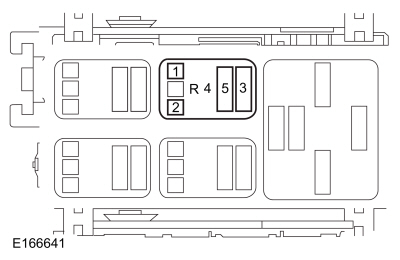 Blower motor relay socket 2
|
Does the test light illuminate?
|
| L4
CHECK THE BLOWER MOTOR RELAY COIL AND SWITCH CONTACT SUPPLY VOLTAGES
|
-
Connect a test light between:
|
Positive Lead
|
Measurement / Action
|
Negative Lead
|
|
Blower motor relay socket 1
|
|
Blower motor relay socket 2
|
|
Blower motor relay socket 3
|
|
Blower motor relay socket 2
|
Does the test light illuminate?
| No
|
For blower motor relay socket 1, VERIFY
fuse 21 (7.5A) is OK. If OK, REPAIR the circuit. If not OK, REFER to the Wiring Diagrams manual to identify the possible
causes of the circuit short.
For blower motor relay socket 3, VERIFY
fuse 4 (40A) is OK. If OK, REPAIR the circuit. If not OK, REFER to the Wiring Diagrams manual to identify the possible causes
of the circuit short.
|
|
| L5
CHECK THE BLOWER MOTOR SPEED CONTROL VOLTAGE CIRCUIT FOR AN OPEN
|
-
Disconnect Blower Motor Speed Control C297A
.
-
Measure:
|
Positive Lead
|
Measurement / Action
|
Negative Lead
|
|
Blower motor relay socket 5
|
|
C297A-4
|
Is the resistance less than 3 ohms?
|
| L6
CHECK THE BLOWER MOTOR SPEED CONTROL GROUND CIRCUIT FOR AN OPEN
|
-
|
Positive Lead
|
Measurement / Action
|
Negative Lead
|
|
C297A-2
|
|
Ground
|
Is the resistance less than 3 ohms?
|
| L7
CHECK THE BLOWER CONTROL PWM (PULSE WIDTH MODULATION)
CIRCUIT FOR A SHORT TO VOLTAGE
|
-
Disconnect
control module C228B
.
-
Measure:
|
Positive Lead
|
Measurement / Action
|
Negative Lead
|
|
C297A-3
|
|
Ground
|
Is any voltage present?
|
| L8
CHECK THE BLOWER CONTROL PWM (PULSE WIDTH MODULATION)
CIRCUIT FOR A SHORT TO GROUND
|
-
Measure:
|
Positive Lead
|
Measurement / Action
|
Negative Lead
|
|
C297A-3
|
|
Ground
|
Is the resistance greater than 10,000 ohms?
|
| L9
CHECK THE BLOWER CONTROL PWM (PULSE WIDTH MODULATION)
CIRCUIT FOR AN OPEN
|
-
Measure:
|
Positive Lead
|
Measurement / Action
|
Negative Lead
|
|
C297A-3
|
|
C228B-18
|
Is the resistance less than 3 ohms?
|
| L10
CHECK THE BLOWER MOTOR CIRCUITS FOR SHORT TO VOLTAGE
|
-
Disconnect Blower Motor Speed Control C297B
.
-
Measure:
|
Positive Lead
|
Measurement / Action
|
Negative Lead
|
|
C297B-1
|
|
Ground
|
|
C297B-2
|
|
Ground
|
Is any voltage present?
| Yes
|
REPAIR the affected circuit.
|
|
| L11
CHECK THE BLOWER MOTOR CIRCUITS FOR SHORT TO GROUND
|
-
Measure:
|
Positive Lead
|
Measurement / Action
|
Negative Lead
|
|
C297B-1
|
|
Ground
|
|
C297B-2
|
|
Ground
|
Are the resistances greater than 10,000 ohms?
| No
|
REPAIR the affected circuit.
|
|
| L12
CHECK THE BLOWER MOTOR CIRCUITS FOR ON OPEN
|
-
Measure:
|
Positive Lead
|
Measurement / Action
|
Negative Lead
|
|
C297B-1
|
|
C2004-1
|
|
C297B-2
|
|
C2004-2
|
Are the resistances less than 3 ohms?
| No
|
REPAIR the affected circuit.
|
|
| L13
CHECK THE BLOWER MOTOR CIRCUITS FOR A SHORT TOGETHER
|
-
Measure:
|
Positive Lead
|
Measurement / Action
|
Negative Lead
|
|
C2004-1
|
|
C2004-2
|
Is the resistance greater than 10,000 ohms?
|
| L14
CHECK FOR CORRECT BLOWER MOTOR SPEED CONTROL OPERATION
|
-
Disconnect and inspect all blower motor speed control connectors.
-
Repair:
-
corrosion (install new connector or terminals – clean module pins)
-
damaged or bent pins – install new terminals/pins
-
pushed-out pins – install new pins as necessary
-
Connect the blower motor speed control connectors. Make sure they seat and latch correctly.
-
Operate the system and determine if the concern is still present.
Is the concern still present?
| No
|
The system is operating correctly at this time. The concern may have been caused by a loose or corroded connector. ADDRESS
the root cause of any connector or pin issues.
|
|
| L15
CHECK FOR CORRECT HVAC (HEATING, VENTILATION AND AIR CONDITIONING)
CONTROL MODULE OPERATION
|
-
Disconnect and inspect all
control module connectors.
-
Repair:
-
corrosion (install new connector or terminals – clean module pins)
-
damaged or bent pins – install new terminals/pins
-
pushed-out pins – install new pins as necessary
-
Connect the
control module connectors. Make sure they seat and latch correctly.
-
Operate the system and determine if the concern is still present.
Is the concern still present?
| Yes
|
CHECK
for any applicable Technical Service Bulletins (TSBs). If a
exists for this concern, DISCONTINUE this test and FOLLOW
instructions. If no Technical Service Bulletins (TSBs) address this concern, INSTALL a new
control module.
REFER to:
Heating, Ventilation and Air Conditioning (HVAC) Control Module
(412-00 Climate Control System - General Information, Removal and Installation).
|
| No
|
The system is operating correctly at this time. The concern may have been caused by a loose or corroded connector. ADDRESS
the root cause of any connector or pin issues.
|
|
The Blower Motor Does Not Operate Correctly
Refer to Wiring Diagrams Cell 55 for schematic and connector information.
Normal Operation and Fault Conditions
Air handling,
REFER to:
Climate Control System - Vehicles With: Electronic Automatic Temperature Control (EATC) - System Operation and Component Description
(412-00 Climate Control System - General Information, Description and Operation).
PINPOINT TEST M : THE BLOWER MOTOR DOES NOT OPERATE CORRECTLY
| NOTICE:
Use the Rotunda Flex Probe kit when making measurements. Failure to use the correct probe adapter(s) may damage the connector.
|
| M1
CHECK THE HVAC (HEATING, VENTILATION AND AIR CONDITIONING)
CONTROL MODULE FOR DIAGNOSTIC TROUBLE CODES (DTCS)
|
-
Using a diagnostic scan tool, perform
control module self-test.
Are any Diagnostic Trouble Codes (DTCs) present?
| Yes
|
REFER to the Diagnostic Trouble Code Charts in this section.
|
|
| M2
VERIFY THE BLOWER MOTOR OPERATION
|
-
Press the panel button on the
controls.
-
Adjust the blower motor speed to LO and then to HI.
Does the blower motor operate in any position?
| Yes
|
If the blower motor operates in HI setting only, GO to
M3
If the blower motor is always ON, CARRY OUT the Relay - Micro ISO component test on the blower motor relay.
Refer to Wiring Diagrams Cell 149 for schematic and connector information.
If the relay tests OK, GO to
M5
|
|
| M3
CHECK THE BLOWER MOTOR VOLTAGE CIRCUIT FOR A SHORT TO VOLTAGE
|
-
Disconnect Blower Motor C2004
.
-
Disconnect Blower Motor Speed Control C297B
.
-
Measure:
|
Positive Lead
|
Measurement / Action
|
Negative Lead
|
|
C297B-1
|
|
Ground
|
Is any voltage present?
|
| M4
CHECK THE BLOWER MOTOR GROUND CIRCUIT FOR A SHORT TO GROUND
|
-
Measure:
|
Positive Lead
|
Measurement / Action
|
Negative Lead
|
|
C297B-2
|
|
Ground
|
Is the resistance greater than 10,000 ohms?
|
| M5
CHECK THE BLOWER CONTROL PWM (PULSE WIDTH MODULATION)
CIRCUIT FOR AN OPEN
|
-
Disconnect Blower Motor Speed Control C297A
.
-
Measure:
|
Positive Lead
|
Measurement / Action
|
Negative Lead
|
|
C297A-3
|
|
C228B-18
|
Is the resistance less than 3 ohms?
|
| M6
CHECK FOR CORRECT BLOWER MOTOR SPEED CONTROL MODULE OPERATION
|
-
Disconnect and inspect all blower motor speed control connectors.
-
Repair:
-
corrosion (install new connector or terminals – clean module pins)
-
damaged or bent pins – install new terminals/pins
-
pushed-out pins – install new pins as necessary
-
Connect the blower motor speed control connectors. Make sure they seat and latch correctly.
-
Operate the system and determine if the concern is still present.
Is the concern still present?
| No
|
The system is operating correctly at this time. The concern may have been caused by a loose or corroded connector. ADDRESS
the root cause of any connector or pin issues.
|
|
| M7
CHECK FOR CORRECT HVAC (HEATING, VENTILATION AND AIR CONDITIONING)
CONTROL MODULE OPERATION
|
-
Disconnect and inspect all
control module connectors.
-
Repair:
-
corrosion (install new connector or terminals – clean module pins)
-
damaged or bent pins – install new terminals/pins
-
pushed-out pins – install new pins as necessary
-
Connect the
control module connectors. Make sure they seat and latch correctly.
-
Operate the system and determine if the concern is still present.
Is the concern still present?
| Yes
|
CHECK
for any applicable Technical Service Bulletins (TSBs). If a
exists for this concern, DISCONTINUE this test and FOLLOW
instructions. If no Technical Service Bulletins (TSBs) address this concern, INSTALL a new
control module.
REFER to:
Heating, Ventilation and Air Conditioning (HVAC) Control Module
(412-00 Climate Control System - General Information, Removal and Installation).
|
| No
|
The system is operating correctly at this time. The concern may have been caused by a loose or corroded connector. ADDRESS
the root cause of any connector or pin issues.
|
|
B1B71:11, B1B71:13
Refer to Wiring Diagrams Cell 55 for schematic and connector information.
Normal Operation and Fault Conditions
The evaporator temperature sensor,
REFER to:
Climate Control System - Vehicles With: Electronic Automatic Temperature Control (EATC) - System Operation and Component Description
(412-00 Climate Control System - General Information, Description and Operation).
Diagnostic Trouble Code (DTC) Fault Trigger Conditions
|
DTC
|
Description
|
Fault Trigger Conditions
|
|
B1B71:11
|
Evaporator Temperature Sensor: Circuit Short to Ground
|
The
senses lower than expected voltage on the sensor feedback circuit, indicating a short to ground.
|
|
B1B71:13
|
Evaporator Temperature Sensor: Circuit Open
|
The
senses greater than expected voltage on the sensor feedback circuit, indicating an open circuit or sensor.
|
Possible Sources
-
Wiring, terminals or connectors
-
Evaporator temperature sensor
-
PINPOINT TEST N : B1B71:11, B1B71:13
| NOTICE:
Use the Rotunda Flex Probe kit when making measurements. Failure to use the correct probe adapter(s) may damage the connector.
|
| N1
CHECK THE IPC (INSTRUMENT PANEL CLUSTER)
OUTPUT VOLTAGE TO THE EVAPORATOR TEMPERATURE SENSOR
|
-
Disconnect Evaporator Temperature Sensor C296
.
-
Select PANEL and press the A/C button (indicator on) on the
controls.
-
Measure:
|
Positive Lead
|
Measurement / Action
|
Negative Lead
|
|
C296-1
|
|
C296-3
|
Is the voltage between 4.7 and 5.1 volts?
|
| N2
CHECK THE EVAPORATOR TEMPERATURE SENSOR
|
-
Allow enough time for the evaporator to stabilize to the ambient temperature.
-
Measure:
|
Positive Lead
|
Measurement / Action
|
Negative Lead
|
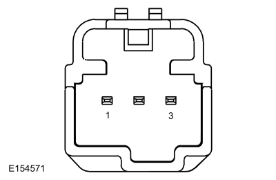 C296-1 (component side)
|
|
C296-3 (component side)
|
-
Compare the resistance values to the table below:
|
Ambient Temperature
|
Resistance
|
|
0-10°C (32-50°F)
|
5,892-9,893 ohms
|
|
10-20°C (50-68°F)
|
3,689-6,048 ohms
|
|
20-25°C (68-77°F)
|
2,950-3,805 ohms
|
|
25-30°C (77-86°F)
|
2,374-3,050 ohms
|
|
30-35°C (86-95°F)
|
1,923-2,460 ohms
|
|
35-40°C (95-104°F)
|
1,566-1,996 ohms
|
|
40-50°C (104-122°F)
|
1,057-1,630 ohms
|
Did the evaporator temperature sensor test OK?
| No
|
INSTALL a new evaporator temperature sensor.
REFER to:
Evaporator Temperature Sensor
(412-00 Climate Control System - General Information, Removal and Installation).
|
|
| N3
CHECK THE EVAPORATOR TEMPERATURE SENSOR CIRCUITS FOR A SHORT TO VOLTAGE
|
-
Measure:
|
Positive Lead
|
Measurement / Action
|
Negative Lead
|
|
C296-1
|
|
Ground
|
|
C296-3
|
|
Ground
|
Is there any voltage present?
| Yes
|
REPAIR the affected circuits.
|
|
| N4
CHECK THE EVAPORATOR TEMPERATURE SENSOR CIRCUITS FOR A SHORT TO GROUND
|
-
Measure:
|
Positive Lead
|
Measurement / Action
|
Negative Lead
|
|
C296-1
|
|
Ground
|
|
C296-3
|
|
Ground
|
Are the resistances greater than 10,000 ohms?
| No
|
REPAIR the affected circuits.
|
|
| N5
CHECK THE EVAPORATOR TEMPERATURE SENSOR CIRCUITS FOR AN OPEN
|
-
Measure:
|
Positive Lead
|
Measurement / Action
|
Negative Lead
|
|
C220A-24
|
|
C296-2
|
|
C220A-26
|
|
C296-1
|
Are the resistances less than 3 ohms?
| No
|
REPAIR the affected circuits.
|
|
| N6
CHECK THE EVAPORATOR TEMPERATURE SENSOR CIRCUITS FOR A SHORT TOGETHER
|
-
Measure:
|
Positive Lead
|
Measurement / Action
|
Negative Lead
|
|
C296-1
|
|
C296-3
|
Is the resistance less than 10,000 ohms?
|
| N7
CHECK THE IPC (INSTRUMENT PANEL CLUSTER)
OPERATION
|
-
Disconnect and inspect the
connector.
-
Repair:
-
corrosion (install new connector or terminals – clean module pins)
-
damaged or bent pins – install new terminals/pins
-
pushed-out pins – install new pins as necessary
-
Connect the
connector. Make sure it seats and latches correctly.
-
Operate the system and determine if the concern is still present.
Is the concern still present?
| Yes
|
CHECK
for any applicable Technical Service Bulletins (TSBs). If a
exists for this concern, DISCONTINUE this test and FOLLOW
instructions. If no Technical Service Bulletins (TSBs) address this concern, INSTALL a new
.
REFER to:
Instrument Panel Cluster (IPC)
(413-01 Instrumentation, Message Center and Warning Chimes, Removal and Installation).
|
| No
|
The system is operating correctly at this time. The concern may have been caused by a loose or corroded connector. ADDRESS
the root cause of any connector or pin issues.
|
|
B105A:11, B105A:15, B1A61:11, B1A61:15
Refer to Wiring Diagrams Cell 55 for schematic and connector information.
Normal Operation and Fault Conditions
In-vehicle temperature sensor,
REFER to:
Climate Control System - Vehicles With: Electronic Automatic Temperature Control (EATC) - System Operation and Component Description
(412-00 Climate Control System - General Information, Description and Operation).
Diagnostic Trouble Code (DTC) Fault Trigger Conditions
|
DTC
|
Description
|
Fault Trigger Conditions
|
|
B105A:11
|
Cabin Temperature Sensor Fan: Circuit Short to Ground
|
The
control module senses lower than expected voltage on the sensor feedback circuit, indicating a short to ground.
|
|
B105A:15
|
Cabin Temperature Sensor Fan: Circuit Short to Battery or Open
|
The
control module senses greater than expected voltage on the sensor feedback circuit, indicating a short to voltage or an open
circuit or sensor.
|
|
B1A61:11
|
Cabin Temperature Sensor: Circuit Short to Ground
|
The
control module senses lower than expected voltage on the sensor feedback circuit, indicating a short to ground.
|
|
B1A61:15
|
Cabin Temperature Sensor: Circuit Short to Battery or Open
|
The
control module senses lower than expected voltage on the sensor feedback circuit, indicating a short to voltage or an open
circuit or sensor.
|
Possible Sources
-
Wiring, terminals or connectors
-
In-vehicle temperature sensor
-
control module
PINPOINT TEST O : B105A:11, B105A:15, B1A61:11, B1A61:15
| NOTICE:
Use the Rotunda Flex Probe kit when making measurements. Failure to use the correct probe adapter(s) may damage the connector.
|
| O1
CHECK THE HVAC (HEATING, VENTILATION AND AIR CONDITIONING)
CONTROL MODULE OUTPUT VOLTAGE TO THE IN-VEHICLE TEMPERATURE SENSOR
|
-
Disconnect In-Vehicle Temperature Sensor C233
.
-
Select PANEL on the
controls.
-
Measure:
|
Positive Lead
|
Measurement / Action
|
Negative Lead
|
|
C233-1
|
|
C233-3
|
Is the voltage between 4.7 and 5.1 volts?
|
| O2
CHECK THE IN-VEHICLE TEMPERATURE SENSOR RESISTANCE
|
-
Measure:
|
Positive Lead
|
Measurement / Action
|
Negative Lead
|
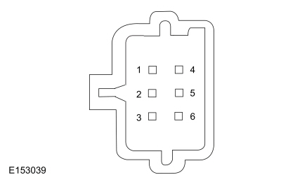 C233-4 (component side)
|
|
C233-6 (component side)
|
-
Compare the resistance values to the table below:
|
Ambient Temperature
|
Approximate Resistance
|
|
-40°C (-40°F)
|
901,490 ohms
|
|
-15°C (5°F)
|
208,450 ohms
|
|
0°C (32°F)
|
95,560 ohms
|
|
15°C (59°F)
|
46,750 ohms
|
|
25°C (77°F)
|
30,000 ohms
|
|
35°C (95°F)
|
19,720 ohms
|
|
60°C (140°F)
|
7,592 ohms
|
|
85°C (185°F)
|
3,286 ohms
|
Did the in-vehicle temperature sensor test OK?
| No
|
INSTALL a new in-vehicle temperature sensor.
REFER to:
In-Vehicle Temperature Sensor
(412-00 Climate Control System - General Information, Removal and Installation).
|
|
| O3
CHECK THE IN-VEHICLE TEMPERATURE SENSOR CIRCUITS FOR A SHORT TO VOLTAGE
|
-
Disconnect
control module C228B
.
-
Measure:
|
Positive Lead
|
Measurement / Action
|
Negative Lead
|
|
C233-1
|
|
Ground
|
|
C233-3
|
|
Ground
|
|
C233-4
|
|
Ground
|
|
C233-6
|
|
Ground
|
Is any voltage present?
| Yes
|
REPAIR the affected circuits.
|
|
| O4
CHECK THE IN-VEHICLE TEMPERATURE SENSOR CIRCUITS FOR A SHORT TO GROUND
|
-
Measure:
|
Positive Lead
|
Measurement / Action
|
Negative Lead
|
|
C233-1
|
|
Ground
|
|
C233-3
|
|
Ground
|
|
C233-4
|
|
Ground
|
|
C233-6
|
|
Ground
|
Are the resistances greater than 10,000 ohms?
| No
|
REPAIR the affected circuits.
|
|
| O5
CHECK THE IN-VEHICLE TEMPERATURE SENSOR CIRCUITS FOR AN OPEN
|
-
Measure:
|
Positive Lead
|
Measurement / Action
|
Negative Lead
|
|
C233-1
|
|
C228B-8
|
|
C233-3
|
|
C228B-9
|
|
C233-4
|
|
C228B-11
|
|
C233-6
|
|
C228B-3
|
Are the resistances less than 3 ohms?
| No
|
REPAIR the affected circuits.
|
|
| O6
CHECK THE IN-VEHICLE TEMPERATURE SENSOR CIRCUITS FOR A SHORT TOGETHER
|
-
Measure:
|
Positive Lead
|
Measurement / Action
|
Negative Lead
|
|
C233-1
|
|
C233-3
|
|
C233-1
|
|
C233-4
|
|
C233-1
|
|
C233-6
|
|
C233-3
|
|
C233-4
|
|
C233-3
|
|
C233-6
|
|
C233-4
|
|
C233-6
|
Are the resistances greater than 10,000 ohms?
| No
|
REPAIR the affected circuits.
|
|
| O7
CHECK FOR CORRECT IN-VEHICLE TEMPERATURE SENSOR OPERATION
|
-
Inspect the disconnected in-vehicle temperature sensor connectors.
-
Repair:
-
corrosion (install new connector or terminals – clean module pins)
-
damaged or bent pins – install new terminals/pins
-
pushed-out pins – install new pins as necessary
-
Connect all in-vehicle temperature sensor disconnected connectors. Make sure they seat and latch correctly.
-
Operate the system and determine if the concern is still present.
Is the concern still present?
| Yes
|
INSTALL a new in-vehicle temperature sensor.
REFER to:
In-Vehicle Temperature Sensor
(412-00 Climate Control System - General Information, Removal and Installation).
TEST the system for normal operation. If the concern is still present, GO to
O8
|
| No
|
The system is operating correctly at this time. The concern may have been caused by a loose or corroded connector. ADDRESS
the root cause of any connector or pin issues.
|
|
| O8
CHECK FOR CORRECT HVAC (HEATING, VENTILATION AND AIR CONDITIONING)
CONTROL MODULE OPERATION
|
-
Disconnect and inspect all
control module connectors.
-
Repair:
-
corrosion (install new connector or terminals – clean module pins)
-
damaged or bent pins – install new terminals/pins
-
pushed-out pins – install new pins as necessary
-
Connect the
control module connectors. Make sure they seat and latch correctly.
-
Operate the system and determine if the concern is still present.
Is the concern still present?
| Yes
|
CHECK
for any applicable Technical Service Bulletins (TSBs). If a
exists for this concern, DISCONTINUE this test and FOLLOW
instructions. If no Technical Service Bulletins (TSBs) address this concern, INSTALL a new
control module.
REFER to:
Heating, Ventilation and Air Conditioning (HVAC) Control Module
(412-00 Climate Control System - General Information, Removal and Installation).
|
| No
|
The system is operating correctly at this time. The concern may have been caused by a loose or corroded connector. ADDRESS
the root cause of any connector or pin issues.
|
|
B1A63:11, B1A63:15, B1A64:11, B1A64:15
Refer to Wiring Diagrams Cell 55 for schematic and connector information.
Normal Operation and Fault Conditions
Sunload sensor,
REFER to:
Climate Control System - Vehicles With: Electronic Automatic Temperature Control (EATC) - System Operation and Component Description
(412-00 Climate Control System - General Information, Description and Operation).
Diagnostic Trouble Code (DTC) Fault Trigger Conditions
|
DTC
|
Description
|
Fault Trigger Conditions
|
|
B1A63:11
|
Right Solar Sensor: Circuit Short to Ground
|
This
sets when the
control module senses lower than expected voltage on the
sensor feedback circuit, indicating a short to ground.
|
|
B1A63:15
|
Right Solar Sensor: Circuit Short to Battery or Open
|
This
sets when the
control module senses greater than expected voltage on the
sensor feedback circuit, indicating a short to voltage or an open circuit or sensor.
|
|
B1A64:11
|
Left Solar Sensor: Circuit Short to Ground
|
This
sets when the
control module senses lower than expected voltage on the
sensor feedback circuit, indicating a short to ground.
|
|
B1A64:15
|
Left Solar Sensor: Circuit Short to Battery or Open
|
This
sets when the
control module senses greater than expected voltage on the
sensor feedback circuit, indicating a short to voltage or an open circuit or sensor.
|
Possible Sources
-
Wiring, terminals or connectors
-
Sunload sensor
-
control module
Visual Inspection and Diagnostic Pre-checks
Inspect loose or corroded
control module and sunload sensor connections.
PINPOINT TEST P : B1A63:11, B1A63:15, B1A64:11, B1A64:15
| NOTICE:
Use the Rotunda Flex Probe kit when making measurements. Failure to use the correct probe adapter(s) may damage the connector.
|
| P1
CHECK THE SUNLOAD SENSOR CIRCUITS FOR A SHORT TO VOLTAGE
|
-
Disconnect
control module C228B
.
-
Disconnect Sunload Sensor C2360
.
-
Measure:
|
Positive Lead
|
Measurement / Action
|
Negative Lead
|
|
C2360-1
|
|
Ground
|
|
C2360-2
|
|
Ground
|
|
C2360-3
|
|
Ground
|
Is any voltage present?
| Yes
|
REPAIR the affected circuits.
|
|
| P2
CHECK THE SUNLOAD SENSOR CIRCUITS FOR A SHORT TO GROUND
|
-
Measure:
|
Positive Lead
|
Measurement / Action
|
Negative Lead
|
|
C2360-1
|
|
Ground
|
|
C2360-2
|
|
Ground
|
|
C2360-3
|
|
Ground
|
Are the resistances greater than 10,000 ohms?
| No
|
REPAIR the affected circuits.
|
|
| P3
CHECK THE SUNLOAD SENSOR CIRCUITS FOR AN OPEN
|
-
Measure:
|
Positive Lead
|
Measurement / Action
|
Negative Lead
|
|
C2360-1
|
|
C228B-2
|
|
C2360-2
|
|
C228B-1
|
|
C2360-3
|
|
C228B-12
|
Are the resistances less than 3 ohms?
| No
|
REPAIR the affected circuits.
|
|
| P4
CHECK THE SUNLOAD SENSOR CIRCUITS FOR A SHORT TOGETHER
|
-
Measure:
|
Positive Lead
|
Measurement / Action
|
Negative Lead
|
|
C2360-1
|
|
C2360-2
|
|
C2360-1
|
|
C2360-3
|
|
C2360-2
|
|
C2360-3
|
Are the resistances greater than 10,000 ohms?
|
| P5
CHECK FOR CORRECT SUNLOAD SENSOR OPERATION
|
-
Inspect the disconnected sunload sensor connectors.
-
Repair:
-
corrosion (install new connector or terminals – clean module pins)
-
damaged or bent pins – install new terminals/pins
-
pushed-out pins – install new pins as necessary
-
Connect all disconnected sunload sensor connectors. Make sure they seat and latch correctly.
-
Operate the system and determine if the concern is still present.
Is the concern still present?
| No
|
The system is operating correctly at this time. The concern may have been caused by a loose or corroded connector. ADDRESS
the root cause of any connector or pin issues.
|
|
| P6
CHECK FOR CORRECT HVAC (HEATING, VENTILATION AND AIR CONDITIONING)
CONTROL MODULE OPERATION
|
-
Disconnect and inspect all
control module connectors.
-
Repair:
-
corrosion (install new connector or terminals – clean module pins)
-
damaged or bent pins – install new terminals/pins
-
pushed-out pins – install new pins as necessary
-
Connect the
control module connectors. Make sure they seat and latch correctly.
-
Operate the system and determine if the concern is still present.
Is the concern still present?
| Yes
|
CHECK
for any applicable Technical Service Bulletins (TSBs). If a
exists for this concern, DISCONTINUE this test and FOLLOW
instructions. If no Technical Service Bulletins (TSBs) address this concern, INSTALL a new
control module.
REFER to:
Heating, Ventilation and Air Conditioning (HVAC) Control Module
(412-00 Climate Control System - General Information, Removal and Installation).
|
| No
|
The system is operating correctly at this time. The concern may have been caused by a loose or corroded connector. ADDRESS
the root cause of any connector or pin issues.
|
|
B10B5:11, B10B5:15
Refer to Wiring Diagrams Cell 55 for schematic and connector information.
Normal Operation and Fault Conditions
Sensor inputs, center register air discharge temperature sensor,
REFER to:
Climate Control System - Vehicles With: Electronic Automatic Temperature Control (EATC) - System Operation and Component Description
(412-00 Climate Control System - General Information, Description and Operation).
Diagnostic Trouble Code (DTC) Fault Trigger Conditions
|
DTC
|
Description
|
Fault Trigger Conditions
|
|
B10B5:11
|
Left Panel Air Discharge Temperature: Circuit Short To Ground
|
This
sets when the
control module senses lower than expected voltage on the sensor feedback circuit, indicating a short to ground.
|
|
B10B5:15
|
Left Panel Air Discharge Temperature: Circuit Short To Battery or Open
|
This
sets when the
control module senses greater than expected voltage on the sensor feedback circuit, indicating a short to voltage or an open
circuit or sensor.
|
Possible Sources
-
Wiring, terminals or connectors
-
Center register air discharge temperature sensor
-
control module
Visual Inspection and Diagnostic Pre-checks
Inspect loose or corroded
control module and center register air discharge temperature sensor connections.
PINPOINT TEST Q : B10B5:11, B10B5:15
| NOTICE:
Use the Rotunda Flex Probe kit when making measurements. Failure to use the correct probe adapter(s) may damage the connector.
|
| Q1
CHECK THE CENTER REGISTER AIR DISCHARGE TEMPERATURE SENSOR CIRCUITS FOR A SHORT TO VOLTAGE
|
-
Disconnect
control module C228B
.
-
Disconnect Center Register Air Discharge Temperature Sensor C2438
.
-
Measure:
|
Positive Lead
|
Measurement / Action
|
Negative Lead
|
|
C2438-1
|
|
Ground
|
|
C2438-3
|
|
Ground
|
Is any voltage present?
| Yes
|
REPAIR the affected circuits.
|
|
| Q2
CHECK THE CENTER REGISTER AIR DISCHARGE TEMPERATURE SENSOR CIRCUITS FOR A SHORT TO GROUND
|
-
Measure:
|
Positive Lead
|
Measurement / Action
|
Negative Lead
|
|
C2438-1
|
|
Ground
|
|
C2438-3
|
|
Ground
|
Are the resistances greater than 10,000 ohms?
| No
|
REPAIR the affected circuits.
|
|
| Q3
CHECK THE CENTER REGISTER AIR DISCHARGE TEMPERATURE SENSOR CIRCUITS FOR AN OPEN
|
-
Measure:
|
Positive Lead
|
Measurement / Action
|
Negative Lead
|
|
C2438-1
|
|
C228B-16
|
|
C2438-3
|
|
C228B-15
|
Are the resistances less than 3 ohms?
| No
|
REPAIR the affected circuits.
|
|
| Q4
CHECK THE CENTER REGISTER AIR DISCHARGE TEMPERATURE SENSOR CIRCUITS FOR A SHORT TOGETHER
|
-
Measure:
|
Positive Lead
|
Measurement / Action
|
Negative Lead
|
|
C2438-1
|
|
C2438-3
|
Is the resistance greater than 10,000 ohms?
|
| Q5
CHECK FOR CORRECT CENTER REGISTER AIR DISCHARGE TEMPERATURE SENSOR OPERATION
|
-
Inspect the disconnected center register air discharge temperature sensor connectors.
-
Repair:
-
corrosion (install new connector or terminals – clean module pins)
-
damaged or bent pins – install new terminals/pins
-
pushed-out pins – install new pins as necessary
-
Connect all disconnected center register air discharge temperature sensor connectors. Make sure they seat and latch correctly.
-
Operate the system and determine if the concern is still present.
Is the concern still present?
| Yes
|
INSTALL a new center register air discharge temperature sensor.
REFER to:
Center Register Air Discharge Temperature Sensor
(412-00 Climate Control System - General Information, Removal and Installation).
TEST the system for normal operation. If the concern is still present, GO to
Q6
|
| No
|
The system is operating correctly at this time. The concern may have been caused by a loose or corroded connector. ADDRESS
the root cause of any connector or pin issues.
|
|
| Q6
CHECK FOR CORRECT HVAC (HEATING, VENTILATION AND AIR CONDITIONING)
CONTROL MODULE OPERATION
|
-
Disconnect and inspect all
control module connectors.
-
Repair:
-
corrosion (install new connector or terminals – clean module pins)
-
damaged or bent pins – install new terminals/pins
-
pushed-out pins – install new pins as necessary
-
Connect the
control module connectors. Make sure they seat and latch correctly.
-
Operate the system and determine if the concern is still present.
Is the concern still present?
| Yes
|
CHECK
for any applicable Technical Service Bulletins (TSBs). If a
exists for this concern, DISCONTINUE this test and FOLLOW
instructions. If no Technical Service Bulletins (TSBs) address this concern, INSTALL a new
control module.
REFER to:
Heating, Ventilation and Air Conditioning (HVAC) Control Module
(412-00 Climate Control System - General Information, Removal and Installation).
|
| No
|
The system is operating correctly at this time. The concern may have been caused by a loose or corroded connector. ADDRESS
the root cause of any connector or pin issues.
|
|
B10B6:11, B10B6:15
Refer to Wiring Diagrams Cell 55 for schematic and connector information.
Normal Operation and Fault Conditions
Sensor inputs, footwell air discharge temperature sensor (footwell air discharge temperature sensor),
REFER to:
Climate Control System - Vehicles With: Electronic Automatic Temperature Control (EATC) - System Operation and Component Description
(412-00 Climate Control System - General Information, Description and Operation).
Diagnostic Trouble Code (DTC) Fault Trigger Conditions
|
DTC
|
Description
|
Fault Trigger Conditions
|
|
B10B6:11
|
Left Floor Air Discharge Temperature: Circuit Short To Ground
|
This
sets when the
control module senses lower than expected voltage on the
sensor feedback circuit, indicating a short to ground.
|
|
B10B6:15
|
Left Floor Air Discharge Temperature: Circuit Short To Battery or Open
|
This
sets when the
control module senses greater than expected voltage on the
sensor feedback circuit, indicating a short to voltage or an open circuit or sensor.
|
Possible Sources
-
Wiring, terminals or connectors
-
Footwell air discharge temperature sensor
-
control module
Visual Inspection and Diagnostic Pre-checks
Inspect loose or corroded
control module and footwell air discharge temperature sensor connections.
PINPOINT TEST R : B10B6:11, B10B6:15
| NOTICE:
Use the Rotunda Flex Probe kit when making measurements. Failure to use the correct probe adapter(s) may damage the connector.
|
| R1
CHECK THE FOOTWELL AIR DISCHARGE TEMPERATURE SENSOR CIRCUITS FOR A SHORT TO VOLTAGE
|
-
Disconnect
control module C228B
.
-
Disconnect Footwell Discharge Air Temperature Sensor C2436
.
-
Measure:
|
Positive Lead
|
Measurement / Action
|
Negative Lead
|
|
C2436-1
|
|
Ground
|
|
C2436-3
|
|
Ground
|
Is any voltage present?
| Yes
|
REPAIR the affected circuits.
|
|
| R2
CHECK THE FOOTWELL AIR DISCHARGE TEMPERATURE SENSOR CIRCUITS FOR A SHORT TO GROUND
|
-
Measure:
|
Positive Lead
|
Measurement / Action
|
Negative Lead
|
|
C2436-1
|
|
Ground
|
|
C2436-3
|
|
Ground
|
Are the resistances greater than 10,000 ohms?
| No
|
REPAIR the affected circuits.
|
|
| R3
CHECK THE FOOTWELL AIR DISCHARGE TEMPERATURE SENSOR CIRCUITS FOR AN OPEN
|
-
Measure:
|
Positive Lead
|
Measurement / Action
|
Negative Lead
|
|
C2436-1
|
|
C228B-7
|
|
C2436-3
|
|
C228B-6
|
Are the resistances less than 3 ohms?
| No
|
REPAIR the affected circuits.
|
|
| R4
CHECK THE FOOTWELL AIR DISCHARGE TEMPERATURE SENSOR CIRCUITS FOR A SHORT TOGETHER
|
-
Measure:
|
Positive Lead
|
Measurement / Action
|
Negative Lead
|
|
C2436-1
|
|
C2436-3
|
Is the resistance greater than 10,000 ohms?
|
| R5
CHECK FOR CORRECT FOOTWELL AIR DISCHARGE TEMPERATURE SENSOR OPERATION
|
-
Inspect the disconnected footwell air discharge temperature sensor connectors.
-
Repair:
-
corrosion (install new connector or terminals – clean module pins)
-
damaged or bent pins – install new terminals/pins
-
pushed-out pins – install new pins as necessary
-
Connect all disconnected footwell air discharge temperature sensor connectors. Make sure they seat and latch correctly.
-
Operate the system and determine if the concern is still present.
Is the concern still present?
| No
|
The system is operating correctly at this time. The concern may have been caused by a loose or corroded connector. ADDRESS
the root cause of any connector or pin issues.
|
|
| R6
CHECK FOR CORRECT HVAC (HEATING, VENTILATION AND AIR CONDITIONING)
CONTROL MODULE OPERATION
|
-
Disconnect and inspect all
control module connectors.
-
Repair:
-
corrosion (install new connector or terminals – clean module pins)
-
damaged or bent pins – install new terminals/pins
-
pushed-out pins – install new pins as necessary
-
Connect the
control module connectors. Make sure they seat and latch correctly.
-
Operate the system and determine if the concern is still present.
Is the concern still present?
| Yes
|
CHECK
for any applicable Technical Service Bulletins (TSBs). If a
exists for this concern, DISCONTINUE this test and FOLLOW
instructions. If no Technical Service Bulletins (TSBs) address this concern, INSTALL a new
control module.
REFER to:
Heating, Ventilation and Air Conditioning (HVAC) Control Module
(412-00 Climate Control System - General Information, Removal and Installation).
|
| No
|
The system is operating correctly at this time. The concern may have been caused by a loose or corroded connector. ADDRESS
the root cause of any connector or pin issues.
|
|
B1A59:11, B1A59:12
Refer to Wiring Diagrams Cell 55 for schematic and connector information.
Normal Operation and Fault Conditions
A 5-volt reference voltage is supplied to the temperature and air distribution door actuators from the
control module.
Diagnostic Trouble Code (DTC) Fault Trigger Conditions
|
DTC
|
Description
|
Fault Trigger Conditions
|
|
B1A59:11
|
Sensor 5 Volt Supply: Circuit Short To Ground
|
This
sets when the
control module senses lower than expected voltage on the reference voltage circuit, indicating a short to ground.
|
|
B1A59:12
|
Sensor 5 Volt Supply: Circuit Short To Battery
|
This
sets when the
control module senses greater than expected voltage on the reference voltage circuit, indicating a short to voltage or an
open circuit or actuator.
|
Possible Sources
-
Wiring, terminals or connectors
-
control module
Visual Inspection and Diagnostic Pre-checks
Inspect loose or corroded
control module connections.
PINPOINT TEST S : B1A59:11, B1A59:12
| NOTICE:
Use the Rotunda Flex Probe kit when making measurements. Failure to use the correct probe adapter(s) may damage the connector.
|
| S1
CHECK THE HVAC (HEATING, VENTILATION AND AIR CONDITIONING)
CONTROL MODULE FOR DIAGNOSTIC TROUBLE CODES (DTCS)
|
-
Using a diagnostic scan tool, perform
control module self-test.
Is
B1A59:11 or B1A59:12 present?
| Yes
|
For B1A59:11, GO to
S2
For B1A59:12, GO to
S3
|
| No
|
For all other Diagnostic Trouble Codes (DTCs), REFER to the
control module
chart in this section.
|
|
| S2
CHECK THE REFERENCE VOLTAGE CIRCUIT AND ACTUATORS RESISTANCE
|
-
Disconnect
control module C228A
.
-
While measuring the resistance, disconnect the following components one at a time, in order. Stop disconnecting components
if the measured resistance rises above 200 ohms.
-
Temperature door actuator
-
Air distribution door actuator
-
Measure:
|
Positive Lead
|
Measurement / Action
|
Negative Lead
|
|
C228A-13
|
|
Ground
|
Did the resistance rise above 200 ohms?
| Yes
|
INSTALL a new actuator (the last one to be disconnected).
REFER to:
Temperature Door Actuator
(412-00 Climate Control System - General Information, Removal and Installation).
or REFER to:
Air Distribution Door Actuator
(412-00 Climate Control System - General Information, Removal and Installation).
|
|
| S3
CHECK THE REFERENCE VOLTAGE CIRCUIT FOR A SHORT TO VOLTAGE
|
-
Disconnect
control module C228A
.
-
Disconnect Temperature Door Actuator C2092
.
-
Disconnect Air Distribution Door Actuator C236
.
-
|
Positive Lead
|
Measurement / Action
|
Negative Lead
|
|
C228A-13
|
|
Ground
|
Is any voltage present?
|
| S4
CHECK FOR CORRECT HVAC (HEATING, VENTILATION AND AIR CONDITIONING)
CONTROL MODULE OPERATION
|
-
Disconnect and inspect all
control module connectors.
-
Repair:
-
corrosion (install new connector or terminals – clean module pins)
-
damaged or bent pins – install new terminals/pins
-
pushed-out pins – install new pins as necessary
-
Connect the
control module connectors. Make sure they seat and latch correctly.
-
Operate the system and determine if the concern is still present.
Is the concern still present?
| Yes
|
CHECK
for any applicable Technical Service Bulletins (TSBs). If a
exists for this concern, DISCONTINUE this test and FOLLOW
instructions. If no Technical Service Bulletins (TSBs) address this concern, INSTALL a new
control module.
REFER to:
Heating, Ventilation and Air Conditioning (HVAC) Control Module
(412-00 Climate Control System - General Information, Removal and Installation).
|
| No
|
The system is operating correctly at this time. The concern may have been caused by a loose or corroded connector. ADDRESS
the root cause of any connector or pin issues.
|
|
U0140:00
Refer to Wiring Diagrams Cell 55 for schematic and connector information.
Normal Operation and Fault Conditions
Control Logic,
REFER to:
Climate Control System - Vehicles With: Electronic Automatic Temperature Control (EATC) - System Operation and Component Description
(412-00 Climate Control System - General Information, Description and Operation).
DTC Fault Trigger Conditions
|
DTC
|
Description
|
Fault Trigger Conditions
|
|
U0140:00
|
Lost Communication With Body Control Module: No Sub-Type Information
|
This
sets in the
control module if data messages received from the
are missing.
|
Possible Sources
-
Vehicle communication bus
-
-
control module
PINPOINT TEST T : U0140:00
| T1
CHECK THE COMMUNICATION NETWORK
|
-
Using a diagnostic scan tool, perform a network test.
Does the
pass the network test?
| No
|
DIAGNOSE the no communication with the
.
REFER to:
Communications Network
(418-00 Module Communications Network, Diagnosis and Testing).
|
|
| T2
RETRIEVE THE RECORDED DIAGNOSTIC TROUBLE CODES (DTCS) FROM THE BCM (BODY CONTROL MODULE)
SELF-TEST
|
-
Using a diagnostic scan tool, perform
self-test.
Is
U3003:16 or
U3003:17 recorded?
|
| T3
RETRIEVE THE RECORDED DIAGNOSTIC TROUBLE CODES (DTCS) FROM THE HVAC (HEATING, VENTILATION AND AIR CONDITIONING)
CONTROL MODULE SELF-TEST
|
-
Check for recorded Diagnostic Trouble Codes (DTCs) from the
module self-test.
Is
U3006:16 or
U3006:17 recorded?
|
| T4
RECHECK THE HVAC (HEATING, VENTILATION AND AIR CONDITIONING)
CONTROL MODULE DIAGNOSTIC TROUBLE CODES (DTCS)
|
-
Clear all Diagnostic Trouble Codes (DTCs).
-
Repeat the
module self-test.
Is
U0140:00 retrieved again?
| No
|
The system is operating correctly at this time. The
may have been set due to high network traffic or an intermittent fault condition.
|
|
| T5
CHECK FOR DTC (DIAGNOSTIC TROUBLE CODE)
U0140:00 SET IN OTHER MODULES
|
-
Using a diagnostic scan tool, clear all Diagnostic Trouble Codes (DTCs).
-
Using a diagnostic scan tool, retrieve all Continuous Memory Diagnostic Trouble Codes (CMDTCs).
Is
U0140:00 set in any other modules?
|
| T6
CHECK FOR CORRECT BCM (BODY CONTROL MODULE)
OPERATION
|
-
Disconnect and inspect all
connectors.
-
Repair:
-
corrosion (install new connector or terminals – clean module pins)
-
damaged or bent pins – install new terminals/pins
-
pushed-out pins – install new pins as necessary
-
Connect the
connectors. Make sure they seat and latch correctly.
-
Operate the system and determine if the concern is still present.
Is the concern still present?
| Yes
|
CHECK
for any applicable Technical Service Bulletins (TSBs). If a
exists for this concern, DISCONTINUE this test and FOLLOW
instructions. If no Technical Service Bulletins (TSBs) address this concern, INSTALL a new
.
REFER to:
Body Control Module (BCM)
(419-10 Multifunction Electronic Modules, Removal and Installation).
|
| No
|
The system is operating correctly at this time. The concern may have been caused by a loose or corroded connector. ADDRESS
the root cause of any connector or pin issues.
|
|
| T7
CHECK FOR CORRECT HVAC (HEATING, VENTILATION AND AIR CONDITIONING)
CONTROL MODULE OPERATION
|
-
Disconnect and inspect all
control module connectors.
-
Repair:
-
corrosion (install new connector or terminals – clean module pins)
-
damaged or bent pins – install new terminals/pins
-
pushed-out pins – install new pins as necessary
-
Connect the
control module connectors. Make sure they seat and latch correctly.
-
Operate the system and determine if the concern is still present.
Is the concern still present?
| Yes
|
CHECK
for any applicable Technical Service Bulletins (TSBs). If a
exists for this concern, DISCONTINUE this test and FOLLOW
instructions. If no Technical Service Bulletins (TSBs) address this concern, INSTALL a new
control module.
REFER to:
Heating, Ventilation and Air Conditioning (HVAC) Control Module
(412-00 Climate Control System - General Information, Removal and Installation).
|
| No
|
The system is operating correctly at this time. The concern may have been caused by a loose or corroded connector. ADDRESS
the root cause of any connector or pin issues.
|
|
U0155:00
Refer to Wiring Diagrams Cell 55 for schematic and connector information.
Normal Operation and Fault Conditions
Control Logic,
REFER to:
Climate Control System - Vehicles With: Electronic Automatic Temperature Control (EATC) - System Operation and Component Description
(412-00 Climate Control System - General Information, Description and Operation).
DTC Fault Trigger Conditions
|
DTC
|
Description
|
Fault Trigger Conditions
|
|
U0155:00
|
Lost Communication With Instrument Panel Cluster (IPC) Control Module: No Sub Type Information
|
This
sets in the
control module if data messages received from the
module are missing.
|
Possible Sources
-
Vehicle communication bus
-
-
control module
PINPOINT TEST U : U0155:00
| U1
CHECK THE COMMUNICATION NETWORK
|
-
Using a diagnostic scan tool, perform network test.
Does the
pass the network test?
|
| U2
RETRIEVE THE RECORDED DIAGNOSTIC TROUBLE CODES (DTCS) FROM THE IPC (INSTRUMENT PANEL CLUSTER)
SELF-TEST
|
-
Using a diagnostic scan tool, perform
self-test.
-
Check for Diagnostic Trouble Codes (DTCs) from the
self-test.
Is
U3006:16 or
U3006:17 recorded?
|
| U3
RETRIEVE THE RECORDED DIAGNOSTIC TROUBLE CODES (DTCS) FROM THE HVAC (HEATING, VENTILATION AND AIR CONDITIONING)
CONTROL MODULE SELF-TEST
|
-
Check for recorded Diagnostic Trouble Codes (DTCs) from the
module self-test.
Is
U3006:16 or
U3006:17 recorded?
|
| U4
RECHECK THE HVAC (HEATING, VENTILATION AND AIR CONDITIONING)
CONTROL MODULE DIAGNOSTIC TROUBLE CODES (DTCS)
|
-
Clear all Diagnostic Trouble Codes (DTCs).
-
Repeat the
module self-test.
Is
U0155:00 retrieved again?
| No
|
The system is operating correctly at this time. The
may have been set due to high network traffic or an intermittent fault condition.
|
|
| U5
CHECK FOR DTC (DIAGNOSTIC TROUBLE CODE)
U0155:00 SET IN OTHER MODULES
|
-
Using a diagnostic scan tool, clear all Diagnostic Trouble Codes (DTCs).
-
Using a diagnostic scan tool, retrieve all Continuous Memory Diagnostic Trouble Codes (CMDTCs).
Is
U0155:00 set in any other modules?
|
| U6
CHECK FOR CORRECT IPC (INSTRUMENT PANEL CLUSTER)
OPERATION
|
-
Disconnect and inspect the
connector.
-
Repair:
-
corrosion (install new connector or terminals – clean module pins)
-
damaged or bent pins – install new terminals/pins
-
pushed-out pins – install new pins as necessary
-
Connect the
connector. Make sure it seats and latches correctly.
-
Operate the system and determine if the concern is still present.
Is the concern still present?
| Yes
|
CHECK
for any applicable Technical Service Bulletins (TSBs). If a
exists for this concern, DISCONTINUE this test and FOLLOW Technical Service Bulletin (TSB) instructions. If no Technical
Service Bulletins (TSBs) address this concern, INSTALL a new
.
REFER to:
Instrument Panel Cluster (IPC)
(413-01 Instrumentation, Message Center and Warning Chimes, Removal and Installation).
|
| No
|
The system is operating correctly at this time. The concern may have been caused by a loose or corroded connector. ADDRESS
the root cause of any connector or pin issues.
|
|
| U7
CHECK FOR CORRECT HVAC (HEATING, VENTILATION AND AIR CONDITIONING)
CONTROL MODULE OPERATION
|
-
Disconnect and inspect all
control module connectors.
-
Repair:
-
corrosion (install new connector or terminals – clean module pins)
-
damaged or bent pins – install new terminals/pins
-
pushed-out pins – install new pins as necessary
-
Connect the
control module connectors. Make sure they seat and latch correctly.
-
Operate the system and determine if the concern is still present.
Is the concern still present?
| Yes
|
CHECK
for any applicable Technical Service Bulletins (TSBs). If a
exists for this concern, DISCONTINUE this test and FOLLOW
instructions. If no Technical Service Bulletins (TSBs) address this concern, INSTALL a new
control module.
REFER to:
Heating, Ventilation and Air Conditioning (HVAC) Control Module
(412-00 Climate Control System - General Information, Removal and Installation).
|
| No
|
The system is operating correctly at this time. The concern may have been caused by a loose or corroded connector. ADDRESS
the root cause of any connector or pin issues.
|
|
U3006:16, U3006:17
Refer to Wiring Diagrams Cell 55 for schematic and connector information.
Normal Operation and Fault Conditions
The
control module is supplied constant voltage and ground. Excessive resistance or an open in one or more of these circuits,
a discharged battery or an inoperative charging system will result in the
control module setting a
.
DTC Fault Trigger Conditions
|
DTC
|
Description
|
Fault Trigger Conditions
|
|
U3006:16
|
Control Module Input Power "A": Circuit Voltage Below Threshold
|
This
sets when the
control module senses lower than expected voltage.
|
|
U3006:17
|
Control Module Input Power "A": Circuit Voltage Above Threshold
|
This
sets when the
control module senses greater than expected voltage.
|
Possible Sources
-
Wiring, terminals or connectors
-
control module
PINPOINT TEST V : U3006:16, U3006:17
| NOTICE:
Use the Rotunda Flex Probe kit when making measurements. Failure to use the correct probe adapter(s) may damage the connector.
|
| V1
CARRY OUT THE HVAC (HEATING, VENTILATION AND AIR CONDITIONING)
CONTROL MODULE SELF-TEST
|
-
Using a diagnostic scan tool, clear Diagnostic Trouble Codes (DTCs).
-
Using a diagnostic scan tool, perform
control module self-test.
Is
U3006:16 or U3006:17 still present?
| No
|
The system is operating correctly at this time. The
may have been set due to a previous low battery voltage condition.
|
|
| V2
RETRIEVE PCM (POWERTRAIN CONTROL MODULE)
DIAGNOSTIC TROUBLE CODES (DTCS)
|
-
Using a diagnostic scan tool, perform
self-test.
Are any charging system Diagnostic Trouble Codes (DTCs) present in the
?
|
| V3
CHECK BATTERY CONDITION
|
-
Carry out the battery condition test.
REFER to:
Battery
(414-01 Battery, Mounting and Cables, Diagnosis and Testing).
Does the battery pass the condition test?
| Yes
|
For
U3006:16, GO to
V4
For
U3006:17, GO to
V6
|
| No
|
INSTALL a new battery.
REFER to:
Battery
(414-01 Battery, Mounting and Cables, Removal and Installation).
|
|
| V4
CHECK THE HVAC (HEATING, VENTILATION AND AIR CONDITIONING)
CONTROL MODULE VOLTAGE SUPPLY CIRCUIT FOR HIGH RESISTANCE
|
-
Disconnect
Control Module C228A
.
-
Measure:
|
Positive Lead
|
Measurement / Action
|
Negative Lead
|
|
C228A-10
|
|
Ground
|
Is the voltage greater than 11 volts?
| No
|
VERIFY
fuse 12 (7.5A) is OK. If OK, REPAIR the circuit. If not OK, REFER to the Wiring Diagrams manual to identify the possible
causes of the circuit short.
|
|
| V5
CHECK THE HVAC (HEATING, VENTILATION AND AIR CONDITIONING)
CONTROL MODULE GROUND CIRCUIT FOR HIGH RESISTANCE
|
-
Measure:
|
Positive Lead
|
Measurement / Action
|
Negative Lead
|
|
C228A-3
|
|
Ground
|
Is the resistance less than 3 ohms?
|
| V6
CHECK FOR CORRECT HVAC (HEATING, VENTILATION AND AIR CONDITIONING)
CONTROL MODULE OPERATION
|
-
Disconnect and inspect all
control module connectors.
-
Repair:
-
corrosion (install new connector or terminals – clean module pins)
-
damaged or bent pins – install new terminals/pins
-
pushed-out pins – install new pins as necessary
-
Connect the
control module connectors. Make sure they seat and latch correctly.
-
Operate the system and determine if the concern is still present.
Is the concern still present?
| Yes
|
CHECK
for any applicable Technical Service Bulletins (TSBs). If a
exists for this concern, DISCONTINUE this test and FOLLOW
instructions. If no Technical Service Bulletins (TSBs) address this concern, INSTALL a new
control module.
REFER to:
Heating, Ventilation and Air Conditioning (HVAC) Control Module
(412-00 Climate Control System - General Information, Removal and Installation).
|
| No
|
The system is operating correctly at this time. The concern may have been caused by a loose or corroded connector. ADDRESS
the root cause of any connector or pin issues.
|
|
Refrigerant System Tests Diagnostic Table
-
NOTE:
The following table is used to guide diagnosis of the refrigerant system if operating pressures are outside normal limits.
NOTE:
Variable compressors operate at lower pressures and are dependent on correct system charge for normal operation.
Refer to the chart below.
|
High (Discharge) Pressure
|
Low (Suction) Pressure
|
Component — Causes
|
|
High
|
Normal to High
|
-
Condenser — inadequate airflow.
-
Engine — overheating.
|
|
Normal to High
|
Normal
|
-
Refrigerant overcharge — air in refrigerant.
|
|
Normal to Low
|
High
|
-
A/C Compressor — low performance.
-
Before condemning the
compressor verify the refrigerant system has the correct system charge.
|
|
Normal to Low
|
Normal to High
|
-
A/C suction line — partially restricted or plugged.
a
|
|
Normal to Low
|
Low
|
-
Low refrigerant charge — leak in system.
-
A/C suction line — partially restricted or plugged.
b
|
|
Erratic Operation or Compressor Not Running
|
-
Ambient Air Temperature (AAT) sensor — poor connection.
-
A/C pressure transducer — poor connection.
-
Evaporator temperature sensor — poor connection.
-
Low refrigerant charge — leak in system.
|
|
Additional Possible Components or Causes Associated With Inadequate Compressor Operation
|
-
Compressor Drive Belt — loose
-
Compressor Clutch — slipping
-
Clutch Coil Open — shorted, or loose mounting
-
Control Assembly Switch — dirty contacts or sticking open
-
Clutch Wiring Circuit — high resistance, open or blown fuse
-
Compressor Operation Interrupted by Engine Computer
|
|
Additional Possible Components or Causes Associated With a Damaged Compressor
|
-
Incorrect Clutch Air-gap
-
Suction Accumulator — refrigerant oil bleed hose plugged
-
Refrigerant Leaks
|
Copyright © Ford Motor Company